INTRODUZIONE
Q)
Laringraziamoper la fiducia che havoluto riservarcie ci complimentiamo con
leiperaverscelto un nostro prodotto. 1Ipresentedispositivo e unTERMOSTATO
MECCANICOsemplice da usare, ehe consente di regolare la temperatura
ambientenelluogo in cui e installato e pertanto e in grado di soddisfare le
esigenzedegli utenti in termini di COMFORTambientale.
CONFORMIT~:Al!~_Ni>BJ-1i:-
- EN60730-'
edaggiornamentisuccessivi
- EN60730-2-9
CONFORMITA'ALLEDIRETTIVE
-B~T73i23T(iE "---
- E.MC.89/336/CEEedaggiornamenti
successivi93/68/CEE
CARATTERISTICHETECNICHE
CAMPODIREGOLAZIONETEMPERATURA~ 5'~30'C
DIFFERENZIALE ~ 0,4K-cO,8K
GRADO DI PROTEZIONE ~ IP 20
CLASSEDIISOLAMENTO~ I
GRADIENTETERMICO~ 1K/15min.
USCITA~ contatti in commutazione
PORTATASUICONTATTI~ 16(2,5)A/250V~
TIPODIAZIONE~ 1B
GRADODI POLLUZIONE~ 2
TEMPERATURA MASSIMA DI SERVIZIO - 50'C
TEMPERATURADI STOCCAGGIO~ O'-c50'C
MONTAGGIO - a parete
TENSIONE NOMINALE D'IMPUlSO ~ 4KV
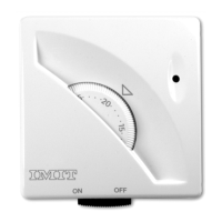
I lEGENDACOMANDIDEl TERMOSTATO
A~ Manopola impostazionetemperatura (fig.l)
B~ led (secondoi modelli)
C~ InterruttoreON/OFF0commutatoreEstate/lnverno(secondoi modelli)
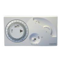
ACCESSORIA RICHIESTA
.Accessorio sottobase -cod. 004095 (fig.3)
.Accessorioperlimite dei campodi regolazione
0 blocco della temperatura impostata ~ cod. 000071 (fig.4)
INSTAlLAZIONEECOllEGAMENTI f!l
Lt.PRESCßIZIONID!2.ICUREZ~ :_--
Primadi collegareil termostato accertarsiehe la tensionedi alimentazione dei
CARICOUTILIZZATOREda comandare (caldaia, pompa, impianto di condi-
zionamento ecc.)NONSIA COlLEGATAe che corrisponda a quella riportata
all'internodell'apparecchio (250V~ max).(fig.5)
POSIZIONAMENTO --. -.--.-.--
Installare il termostato lontano da fonti di calore (caloriferl, raggi solari,
cucine)eda porte/finestre, a circa 1,5mt dal pavimento. (fig.G)
INSTALLAZIONE i:C°l!.E..§_~~i:NTIJlJ:ITBIQ .
A)In casodi installazione su scatola tonda interasseGOmm,su superficie non
perfettamentepiana0 in altri casi particolari, utllizzare I'accessoriosottobase
(vederecapitolo "Accessoria richiesta").Fissarlomediante unacoppla di forl
adeccezionedi B-B,previstl per il termostato. (fig.7)
B)Separarela basedalcoperchio dei prodotto facendo pressionesull'apposito
dentedi aggancio(fig.8), quindi fissarla alla parete (0 alla sottobase)utiliz-
zandoi fori a disposizione(fig.9) a mezzoviti con un diametro max 3,5mm.
C)Portarei fili dell'impiantoattraversolaferitoia praticata sullabaseed eseguire
gli allacciamentialla morsettierain conformita allo schemaelettrico riportato
all'internodeiprodotto; riagganciareIIcoperchioalla base.(fig.l0)
Lt.ATTENZIONE:
SIraccomandadi eseguireI'installazionedei termostato rispettando scrupolo-
samentele norme di sicurezzae le disposizionl di leggevigenti.
INTRODUCTION
@
Thank you for your confidence in our Company and for choosing one of our
products. This is an easy-to-use MECHANICAl THERMOSTAT.It allows an
accurate room temperature adjustment in the hosting room, thus meeting
any users' needsasfar as room comfor!.
CQ~FQß}""I1IIQJ!:IU:ffit!Q.i\IiD?
Thisproductcomplieswith:
- EN60730-'andsubsequent
revisions
- EN60730-2-9
CONFORMITYTOTHE GUIDELINES
--"-' "---" '-'---"-"-"
This product complies with:
- BT 73/23/EEC
- E.MC.89/336/EEC
and later updating of 93/68/EEC
TECHNICAlDATA
TEMPERATURERANGE~ 5'-c30'C
TEMPERATUREDIFFERENTIAL~ 0,4K-cO,8K
DEGREE OF PROTECTION -IP 20
INSULATIONCLASS~ I
TEMPERATURERATEOFCHANGE
~ 1K/15min.
OUTPUT~ switching contacts
CONTACTSRATING~ 16(2,5)A/250V~
SWITCHACTION- 1B
POLLUTIONDEGREE- 2
MAXIMUM STANDINGTEMPERATURE- 50'C
STORAGETEMPERATURE- O'-c50'C
MOUNTING- to the wall
RATEDIMPULSEVOlTAGE-4KV
THERMOSTATCONTROlKEYS
A -Temperature setting knob (fig.l)
B
-Warning lamp
C ~ ON/OFFswitch or SUMMER/WINTERswitch (depending on models)
OPTIONAlACCESSORIES
.Sub-basefitting -cod. 004095(fig.3)
.Specialfitting for temperaturerangerestrietionsorforthe
temperature lock at apre-set value. -cod. 000071(fig.4)
INSTALLATIONANDCONNECTIONS ~
4~~FJD'JN~IßU.cIIQI':!~ ,-- , -'.- ___"M" -
Before connecting the thermostat, make sure that the supply voltage of the
UNITTOBECONTROlLED(boiler, pump, air-conditioning system, etc.) is NOT
CONNECTEDand that it matches the indication given inside the appliance
(250V~ maxI. (fig.S)
PLACEMENT OF THE THERMOSTAT
'-'---'--""'-"""-'--'-""'-'-'-'---' '-'---------..
Install the thermostat awayfrom heat sources(radiators,sumays,and kitchens)
and away from doors/windows, at approx. 1,5m height from the floor. (fig.G)
!1':!.~I~_L!ATL°..N.l\Ng,_~!B~§SONN~fIl9..N~___-----_.__.
A) In case the thermostat shall be installed either in a round built-in box
(havingdistancebetweencentresequal to 60mm),or on an unevenwall surface
or in other particular locations, it is recommended to use a sub-base fitting
(seeparagraph "Optional Accessories"). Fixthe fitting to the wall through two
holes other than the ones marked as B-B, which are exclusively provided for
the thermostat installation. (fig.7)
B) Removethe front cover from the thermostat baseby releasingthe provided
clip (fig.8), then fix it to the wall (or to the sub.base fitting) through the
provided holes(fig.9) and tighten it by means of suitable screws having max
of 3,5 mm.
C)Thread the power supply wires through the slot in the baseand connect
them to the terminals asper the wiring diagram sketchedinsidethe appliance.
Snap the front cover back.(fig.l0)
LhWARNING:
It is recommendedto install the appliancestrictly in compliance with all safety
and law provisions in force.
 Loading...