1-11
1
1
2
3
4
6
5
7
8
9
9
INSTALLERUSER
MAINTENANCE TECHNICIAN
Pump anti-seizure
Audax TOP ErP units are equipped with an an-
ti-seizure protection of the pump's motor sha.
For this function to operate correctly, the system
must not be emptied and supply voltage must not
be disconnected during long periods of inactivity.
However, if the pump rotor sha should seize
after long periods of inactivity, the operator
should do as follows in order to release it (only
for Audax TOP 12-16 ErP):
- Disconnect voltage
- Remove the front panel
- Loosen the sha's protection cap at the rear
of the pump
- Insert a at-blade screwdriver into the groove
and turn the rotor's sha
- Reassemble the protection cap
- Supply voltage to the system
Cleaning the system and Water features
With new installations or when emptying the
circuit, preventive cleaning of the system must
be carried out.
In order to ensure proper operation of the prod-
uct, aer each cleaning operation, replace water
or top up glycol. Make sure the liquid is clear, is
without any visible impurities and the hardness
is below 20°f.
Antifreeze protection
If the device is kept o during the winter months
with the room temperature below 0°C and glycol
is not used in the hydraulic system, it is recom-
mended to empty the entire system by draining
the unit (Fig. 1-9, point 3) and the system's
discharge valve (Fig. 1-11, point 5).
System minimum water content
Minimum water content is mainly important to
provide proper execution of defrosting cycles.
In this regard, the minimum amount of water
to ensure is:
AUDAX TOP 6-8-12-16 ErP → 6 l/kW for any
type of system.
N.B.: it is also important to check that the
dehumidier line has a minimum of 3 l/kW
(dehumidier hydraulic circuit connection).
Pipe content
Inside diameter External diameter Litres/metre
Copper
12 mm) 14 mm) 0.11 l/m
14 mm) 16 mm 0.15 l/m
16 mm) 18 mm 0.20 l/m
20 mm) 22 mm 0.31 l/m
25 mm) 28 mm) 0.49 l/m
32 mm) 35 mm 0.80 l/m
Steel
“12.7 mm (1/2”)” 3/8” Gas 0.13 l/m
“16.3 mm (5/8”)” 1/2” Gas 0.21 l/m
“21.7 mm (7/8”)” 3/4” Gas 0.37 l/m
“27.4 mm (11/16”)” 1” Gas 0.59 l/m
Unit Audax TOP ErP
6 8 12 16
Nominal water
input
Std l/s 0.28 0.33 0.58 0.69
Operating Pressure Max kPa 300 300 300 300
Filling pressure Min kPa 120 120 120 120
Unit lowest level
dierence
Max m 20 20 20 20
% Glycol 10% 20% 30% 40%
Freezing Temperature (*) -4 °C -9 °C -15 °C -23 °C
Correction
Factors
Capacity 0.996 0.991 0.983 0.974
Absorbed Power 0.990 0.978 0.964 1.008
Heat loss 1.003 1.010 1.020 1.033
(*) N.B.: the temperature values are indicative.
Always refer to the temperature levels indicated regarding the specic product used.
TABLE USED TO CALCULATE THE WATER CONTENT IN THE SYSTEM
Installed Unit
Unit content (*) I
Pipe content (**) I
Utilities (fan coils, panels, radiators, etc.) (***) I
Total content (****) I
(*) Consult the technical specications table
(**) Consult the water pipes content table
(***) Consult the manual regarding utilities
installed
(****) e content of water in the system must be
above 6 litres per kW of machine power
(e.g. Audax TOP 12kW, 6x12 = more than 72
litres).
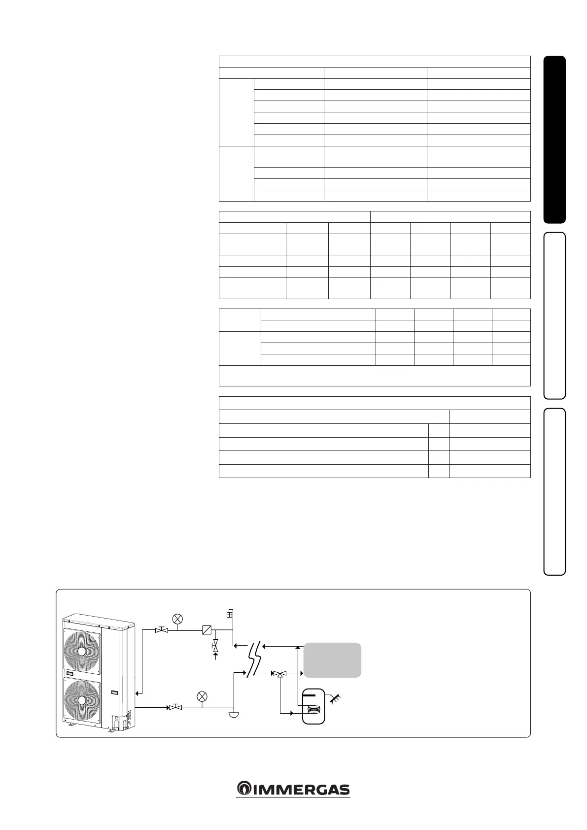
Key:
1 - Shut-o valve
2 - Water line lters (10 links/cm
2
)
3 - Manometer
4 - Filling valve
5 - System draining valve (in the lowest points of the
circuit)
6 - Air vent valve (in the highest points of the circuit)
7 - 3-way valve
8 - DHW storage tank
9 - Internal utility
Typical diagram of a hydraulic circuit for Audax TOP ErP units
Attention: do not use the heat pump to treat
industrial process water, swimming pool water
or DHW.
In all these cases, provide an intermediate heat
exchanger.

 Loading...