Do you have a question about the Immergas EOLO Eco Series and is the answer not in the manual?
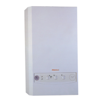
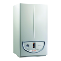
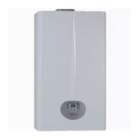
Description of the EOLO Eco kW boiler, including its ecological class, burner type, power variants, and control system.
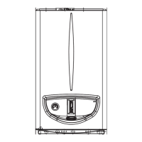
Diagrams and specifications for the boiler's physical dimensions and external connection points for gas, water, and electricity.
Overview of the boiler's control panel, detailing buttons, knobs, and LED indicators for status and malfunctions.
Detailed diagram and legend of the main internal components of the EOLO Eco kW boiler.
Schematic representation of the boiler's hydraulic circuit, illustrating water flow and component connections.
Explanation of the primary circuit's heat transfer and water flow, including the 3-way valve's role.
Graphs illustrating the system's flow-head ratio based on pump speed and by-pass adjustment.
Description and illustration of the boiler's circulator, its function, and integration.
Details on the primary water-gas exchanger, including its construction and connected probes/thermostats.
Explanation of the motorised 3-way diverter valve's operation, role in switching water flow, and its components.
Description of the adjustable by-pass device, its function in circulation, and adjustment method.
Details on the system filling unit, its function for pressurising the heating system, and connections.
Explanation of the system pressure switch, its role in monitoring pressure and preventing burner operation.
Description of the automatic air vent, its function to expel gases from the boiler circuit.
Information on the 3-bar safety valve, its function to prevent exceeding safety pressure.
Details on the system expansion vessel, its role in compensating volume changes and reducing pressure changes.
Explanation of the DHW circuit's operation, including the priority function and heat exchange process.
Explanation of the DHW flow switch, its activation trigger, and flow limiting device.
Description of the water-water heat exchanger used for DHW production, detailing its construction and connections.
Explanation of the gas circuit, burner operation, air-gas mix, and emission reduction.
Details on the modulating gas valve, its coils, and pressure regulation capabilities.
Information on the ON-OFF type electrical coils for burner ignition and their power supply.
Description of the modulation coil's role in controlling gas valve stabiliser and outlet pressure.
Description of the burner's construction, nozzles, cooling, and diaphragm plate for optimal combustion.
Details on the ignition electrode's function and connection to the integrated board for sparking.
Information on the detection electrode's role in detecting burner ignition and its connection.
Procedure for adjusting maximum and minimum gas pressure, including required tools and measurements.
Specific instructions for adjusting maximum and minimum pressure on the SIT 845 gas valve.
Steps for converting the boiler to different gas types, including nozzle changes and selector adjustments.
Explanation of flue gas path, efficiency increase, and draught diverter function.
Description of the flue pressure switch, its function in detecting pressure differences for safe operation.
Details on the air-flue intake traps for sampling combustion air and flue, and their pressure points.
Information on the pressure points used to measure signals for the flue pressure switch.
Explanation of the fan's operation for flue extraction and air intake, and its control mechanism.
Overview of air inlet and exhaust configurations (sealed/open chamber) and connection types.
Details on installing the boiler outdoors in a partially protected place using the open chamber configuration.
Information on connecting the exhaust pipes, including push-fitting, flange types, and pipe length limitations.
Details on connecting the air inlet pipes, including split system, coaxial pipes, and unused hole closure.
Description of connecting the boiler in a fan-assisted sealed chamber configuration, including flange and flue shutter adjustments.
Diagram illustrating the electrical connections and components active during the central heating phase.
Overview of the 230V AC circuit components and their function within the boiler's electrical system.
Description of key safety devices and controls within the electrical circuit, such as fuses and electrodes.
Details on the boiler circulator, its power source, and function in primary circuit water circulation.
Description of the ignition electrode's role in producing an electric discharge for burner ignition.
Information on the integrated board's continuous power supply and its central control function.
Details on the optional central heating timer, its function in enabling/preventing operation during set intervals.
Explanation of the 3-way diverter valve's function in diverting primary circuit water flow.
Information on the gas valve's main coils, their power supply, and role in allowing gas passage.
Description of the fan's function to ensure air flow and extract flue gases, and its power source.
Details on the optional zone control unit for managing multiple heating zones and room thermostats.
Information on the optional remote control for managing boiler functions and settings remotely.
Description of the DHW flow switch's role in enabling the DHW phase and its interaction with the central heating phase.
Explanation of the system pressure switch's function to cut power to K2 relay if pressure is too low.
Details on the flue pressure switch's action on the integrated board for enabling/preventing burner ignition.
Explanation of the main selector switch positions (Summer, Winter, Reset) and their functions.
Information on the optional external probe for detecting external temperature and adjusting system delivery.
Description of the delivery NTC probe for detecting primary circuit delivery water temperature.
Details on the DHW NTC probe for measuring domestic hot water outlet temperature and fault signalling.
Explanation of the optional room thermostat's role in enabling central heating based on room temperature.
Details on the optional central heating timer for controlling operation at set times.
Information on the safety thermostat's function to shut off the burner when safety temperature is exceeded.
Description of the gas valve modulator's DC signal for controlling gas pressure to the burner.
Explanation of how the electrical circuit operates during the central heating phase, including component activation.
Details on how the boiler operates in central heating mode when controlled by a room thermostat.
Explanation of boiler operation in central heating phase when using the remote control (CAR).
Explanation of the electrical circuit's operation during the domestic hot water phase, including component activation.
Detailed explanation of the integrated board's operation during a central heating request, including sequence and parameters.
Explanation of integrated board response to DHW requests, including flow switch and temperature settings.
Explanation of how the integrated board manages heating antifreeze requests and minimum output operation.
Details on the integrated board's response to domestic hot water antifreeze requests and minimum power operation.
Information on the 'Chimneysweep' function, its activation via the selector switch, and operational parameters.
Signals sent by the zone control unit regarding zone valves or external pumps.
Signals from the remote control concerning selector switch, temperature, and requests.
Indication of ongoing request (DHW or central heating) and priority of DHW phase.
Input from the timer switch enabling or preventing central heating operation at set times.
Action of the pressure switch cutting power to K2 relay if primary circuit pressure is below 0.3 bar.
Input enabling burner ignition by powering K2 relay when flues are expelled correctly.
Signal indicating flame detection, allowing modulation coil current increase.
Resistor input varying with external temperature, enabling system delivery temperature changes.
Resistor input inversely proportionate to primary circuit delivery water temperature; used as limit thermostat.
Resistor input inversely proportionate to DHW outlet temperature.
Input signal enabling central heating when room temperature is below requested level.
230V AC signal indicating main gas valve coils are energised.
High voltage signal (16 kV) for electrical discharge at ignition electrodes.
Signal to zone control unit indicating appliance status (DHW/heating) and CAR recognition.
Signal (BUS) for remote display of boiler temp, phase, alarms, and external probe temp.
DC signal controlling modulation coil to vary gas pressure to burner.
Unipolar relay controlling the circulator (M30), energised when requested.
Bipolar relay excited for burner ignition, enabling ignition via its contact.
Relay powering the 3-way diverter valve motor (M); excited for central heating, idle for DHW.
Unipolar relay controlling the fan (M20), excited when its operation is requested.
Allows programmer clock to be powered at 230 Vac; signal always present regardless of selector switch position.
Adapts modulating parameters to the type of gas (Natural Gas/LPG) the boiler is set for.
Antilock function for circulator and 3-way diverter valve after periods of inactivity.
Boiler operation interruption if flame is not detected within 10 seconds of ignition.
Boiler stoppage if flue pressure switch contact opens while fan is working.
Boiler operation blocked if the overheating safety thermostat contact opens.
Burner shutdown if temperature increases rapidly due to blocked pump or low water.
Circulator continues working for 150 seconds after central heating, antifreeze, or 'chimneysweep' requests.
Combustion chamber washed and fan running for 30 seconds after burner switch-off.
Protection against NTC probe breakage affecting central heating or DHW operation.
Fan switches on if delivery temperature exceeds 90°C to prevent exchanger overheating.
Description of LED indicators and remote display codes for boiler status and operation.
Table detailing LED flashing patterns and remote display codes for various malfunctions.
List of parameters that can be programmed on the integrated board, with corresponding LED indicators.
Instructions for setting the minimum heating output parameter using LED indicators and temperature knob.
Instructions for setting the maximum heating output parameter using LED indicators and temperature knob.
Setting for the electronic timer to prevent frequent burner ignition in central heating.
Instructions for setting the central heating ignition timer using LED indicators.
Setting for delaying central heating ignition requests from room thermostat or remote control.
Setting the time for the boiler to ramp up from minimum to maximum central heating output.
Setting for correlated or fixed domestic hot water thermostat modes.
Selection between intermittent or continuous circulator operation in the central heating phase.
Enabling the DHW exchanger preheating function to maintain a constant temperature for quicker hot water supply.
Function to adjust boiler parameters for working with first family gases (China Gas).
Configuration options for Relay 1 operation, including zone command, alarms, and gas valve status.
Configuration options for Relay 2 operation, including remote filling, alarms, and zone commands.
Configuration options for Relay 3 operation, including Aqua Celeris, general alarm, and heating phase.
Step-by-step operational sequence for the central heating phase, from power on to boiler working.
Step-by-step operational sequence for the domestic hot water phase, from power on to boiler working.
Technical specifications related to electrical connections for the 24 kW model.
Technical specifications related to electrical connections for the 28 kW model.
Performance data for the EOLO Eco 24 kW model across various heat outputs and gas types.
Performance data for the EOLO Eco 28 kW model across various heat outputs and gas types.





 Loading...