13
STEEkW ed 01/06 EOLO Extra kW
Technical Documentation
Technical Documentation
is circuit consists of an atmospheric burner and a modulat-
ing gas valve that permit, respectively, the combustion of gas
and the regulation of its flow rate.
Operation.
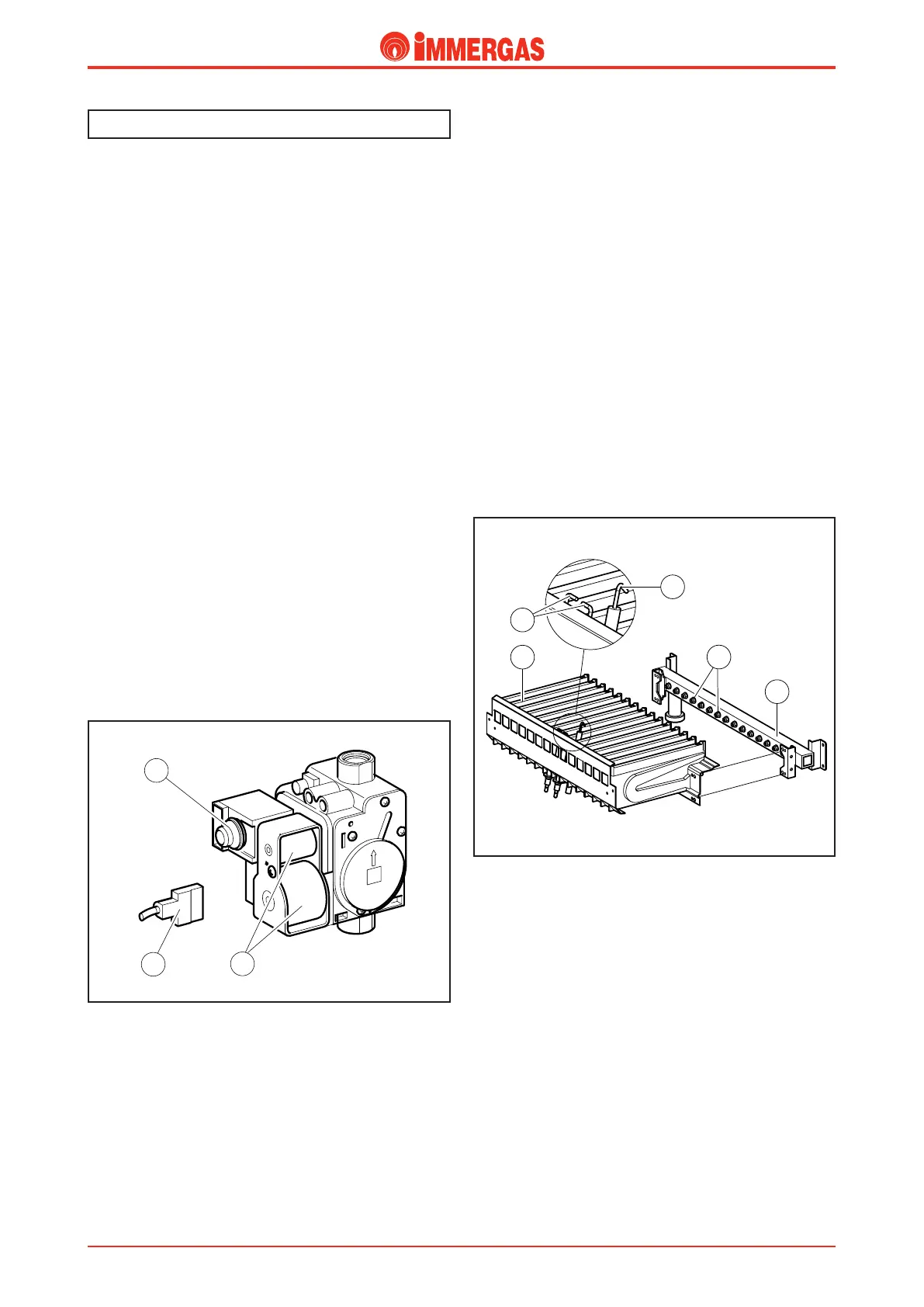
When the main coils (3) are powered it causes both shutters
inside the valve to open which lets gas through to the burner.
Consequently the flow rate/pressure in output is adjusted by
acting on the gas valve stabiliser by means of the modulation
coil (1). e gas is injected into the horizontal Venturi pipes
(shafts) through the burner nozzles (7). e air-gas mixture
is created inside these pipes and set alight by the discharge of
the ignition electrodes (5).
Modulating gas valve.
e gas valve (SIT 845) features two main coils (3) and a
modulation coil (1) controlled by the integrated board.
e maximum and minimum outlet pressure settings can be
made on this valve (see gas regulations).
Main electrical coils (3).
ey are two ON-OFF type coils energised (230 Vac) by the
integrated board when the burner has to be ignited.
ey are electrically connected in parallel and energised by
mains power through a special connector (2).
Modulation coil (1).
is low-voltage coil is controlled by the integrated board.
It controls the gas valve stabiliser and is used to change the
outlet pressure in a way proportionate to the dc current that
runs through it.
Gas circuit.
Burner.
e burner consists of horizontal Venturi pipes (6) inside which
gas is injected by the same number of nozzles (7) mounted on
the respective manifold (8).
e diameter of the nozzles (7) varies according to the type of
gas utilised (see technical data).
e number of the nozzles is 11 (24 kW version), 14 (28 kW
version) and 15 (32 kW version).
Ignition electrodes (5).
ey are controlled by the integrated board that produces an
electric discharge between the electrodes.
ey are positioned on the front of the burner.
Detection electrode (4).
It is controlled by the integrated board and detects burner
ignition.
It is positioned on the front of the burner beside the ignition
electrodes.
 Loading...


