3
LP
GP
AC
AF
SC
LP
GP
AF
AC
SC
1
6
INSTALLERUSERMAINTENANCE TECHNICIAN
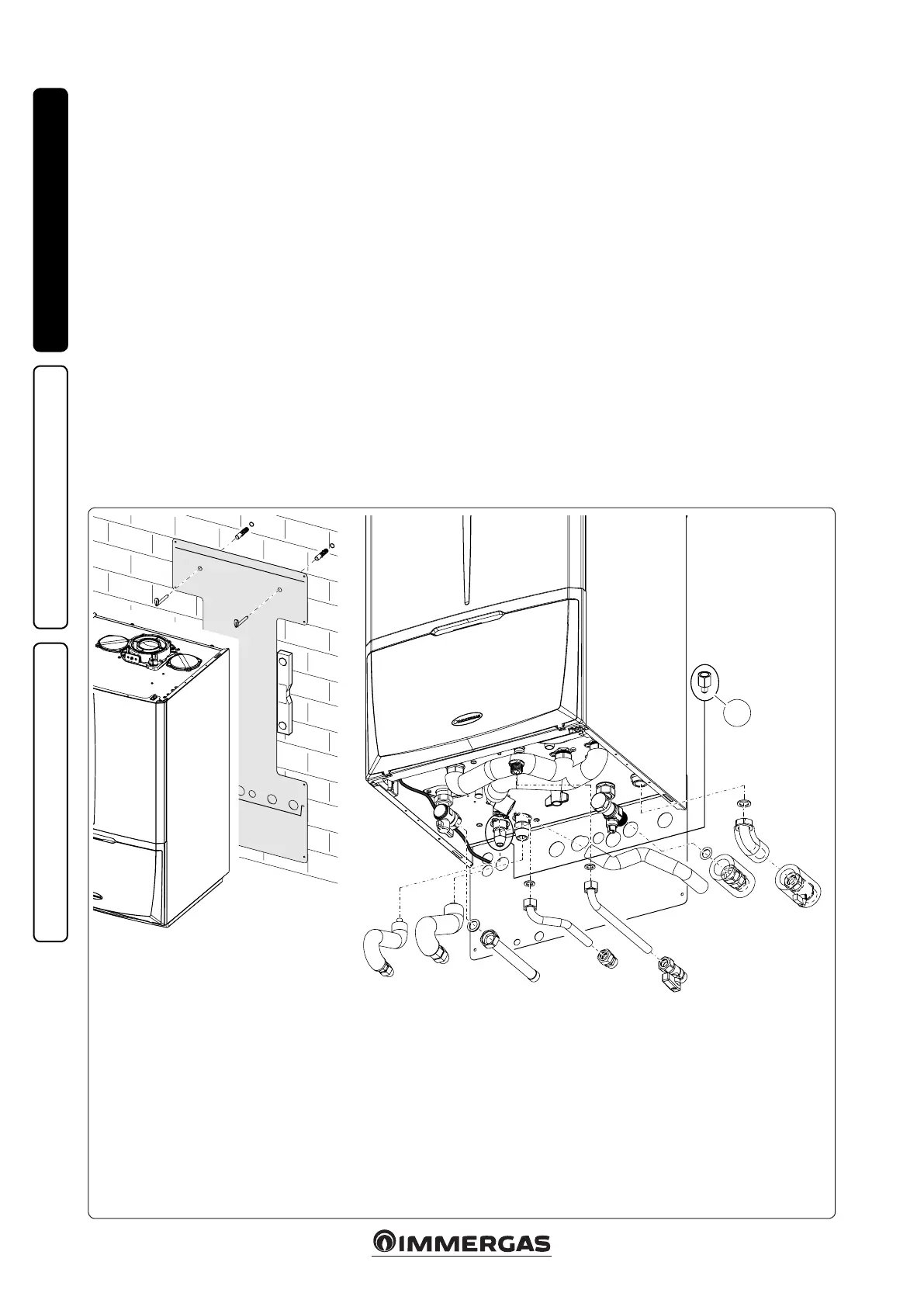
e hydraulic connection kit includes:
N° 2 - adjustable expansion bolts
N° 2 - indoor unit support hooks
N° 1 - Gas supply pipe Ø 18 (G)
N° 1 - cold water inlet pipe 1/2” (AF)
N° 1 - hot water outlet pipe 1/2”(AC)
N° 1 - 1/2” ball valve (AF)
N° 1 - 3/4” system return pipe (R)
N° 1 - 3/4” system ow pipe (M)
N° 1 - 3/4” ball valve (M)
N° 3 - Insulating sheath for system pipes (R - M)
N° 1 - Telescopic tting 1/2” (AC)
N° 1 - 3/4” telescopic tting (R)
Gaskets, screws and seal O-Ring
1.4 CONNECTION GROUP.
- e hydraulic connection unit is standard sup-
plied with Magis Combo. Make the hydraulic
connection as shown below, making sure to
protect the system ow and return pipes with
their supplied insulating sheaths.
- The R410A circuit wall connection unit is
supplied as an extra kit. Connect the circuit,
following the instructions provided in the
condensing unit instructions booklet.
1.5 HYDRAULIC CONNECTION.
Attention: in order not to void the product war-
ranty, before making unit connections, carefully
clean the heating system (pipes, radiators, etc.)
with special pickling or de-scaling products to
remove any deposits that could jeopardise proper
indoor unit operation.
Treatment of the thermal system water is re-
quired by law, in order to protect the system and
the appliance from deposits (e.g., lime scale),
slurry or other hazardous deposits. Water con-
nections must be made in a rational way using the
couplings on the indoor unit template.
Water connections must be made in a rational
way using the couplings on the indoor unit
template. e safety valve outlet of the indoor
unit must be connected to a draining funnel.
Otherwise, the manufacturer of the indoor unit
declines any responsibility in case of ooding if
the drain valve cuts in.
Attention: the manufacturer declines all liability
in the event of damage caused by the installation
of an automatic lling system.
In order to meet the system requirements es-
tablished by EN 1717 regarding the pollution
of drinking water, we recommend installing the
IMMERGAS anti-backow kit upstream of the
hydronic unit cold water inlet connection. We
also recommend using a category 1, 2 or 3 heat
transfer uid (ex: water + glycol) in the hydronic
unit primary circuit (CH circuit), as dened in
the EN 1717 standard.
Attention: to preserve appliance duration and
eciency features, we recommend installing a
suitable water treatment device if the water has
features that can lead to limescale deposits.
Condensate drain. To drain the condensate pro-
duced by the appliance, it is necessary to connect
to the drainage system by means of acid conden-
sate resistant pipes, with an internal Ø of at least
13 mm. e system connecting the appliance to
the drainage system must be carried out in such
a way as to prevent occlusion and freezing of the
liquid contained in it. Before appliance ignition,
ensure that the condensate can be correctly re-
moved. Aer rst ignition, check that the drain
trap is lled with condensate (Para. 1.23). Also,
comply with national and local regulations on
discharging waste waters.
In the event condensate is not discharged into
the wastewater drainage system, a condensate
neutraliser must be installed to ensure com-
pliance with the parameters established by the
legislation in force.
Attention: if you are using one or more booster
pumps it is essential to install a hydraulic sep-
arator (not supplied by Immergas) downstream
of the indoor unit.
e R410A circuit wall connection kit (optional)
includes:
N° 1 - G 3/8” liquid phase chiller line pipe (LP)
N° 1 - G 5/8” gaseous phase chiller line pipe (GP)
Already installed on the module:
N° 1 - Gas cock
N° 1 - System interception tap with 3/4” lter (R)
Key:
V - Electrical connection
G - Gas supply
AC - Domestic hot water outlet
AF - Domestic cold water inlet
SC - Condensate drain (minimum internal diame-
ter Ø 13 mm)
R - System return
M - System ow
LP - Chiller line - liquid phase
GP - Chiller line - gaseous phase
1 - G 3/8"F - 1/4" SAE M reduction
(supplied with Audax Pro 5kW; to be used
only in pairing with this model)

 Loading...