28
19
INSTALLERUSERMAINTENANCE TECHNICIAN
1.21 FLUES, CHIMNEYS, CHIMNEY POTS
AND TERMINALS.
e ues, chimneys and chimney pots for the
evacuation of combustion products must be in
compliance with applicable standards. Chimneys
and roof-installed exhaust terminals must com-
ply with the outlet height and with the distance
from technical volumes set forth by the technical
standards in force.
Positioning the wall ue exhaust terminals. e
wall ue exhaust terminals must:
- be installed on external perimeter walls of the
building;
- be positioned according to the minimum dis-
tances specied in current technical standards.
Combustion products exhaust of natural
draught or fan assisted appliances in open-top
closed environments. In spaces closed on all
sides with open tops (ventilation pits, court-
yards etc.), direct combustion product exhaust
is allowed for natural draught or fan assisted gas
appliances with a heat input range from 4 to 35
kW, provided the conditions as per the current
technical standards are respected.
1.22 FILLING THE SYSTEM.
Once the indoor unit is connected, ll the heating
system using the lling cock (Fig. 30). Filling
must be done slowly to allow the air bubbles
in the water to escape through the vents in the
indoor unit and the heating and air conditioning
system.
e indoor unit has one incorporated automatic vent
valve located on the circulator and another on the
central heating manifold. Make sure that the hoods
are loosened.
e lling cock must be closed when the indoor
unit pressure gauge indicates approximately
1.2 bar.
N.B.: during these operations, enable the "Vent-
ing" functions by setting the "M01" parameter to
ON, which lasts about 18 hours (see paragraph
3.10).
System minimum water content.
Minimum water content is mainly important to
provide proper execution of defrosting cycles.
To this end, the minimum amount of water to
guarantee is 7 l/kW for any type of system.
N.B.: it is also important to check that the
dehumidier line has a minimum of 3 l/kW
(dehumidier hydraulic circuit connection).
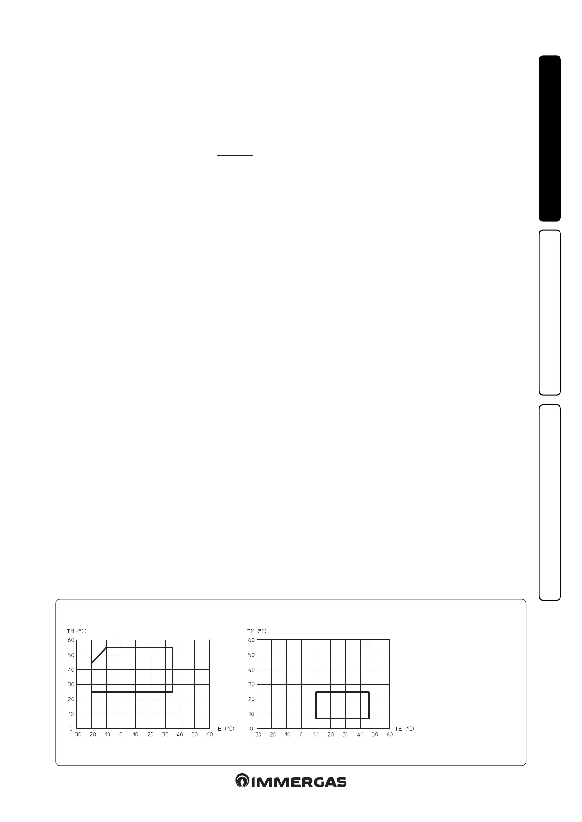
Heat pump operating limits during the heating mode. Heat pump operating limits during the cooling mode.
Key:
TE = Outside temperature
TM = Flow temperature
1.23 FILLING THE CONDENSATE DRAIN
TRAP.
On rst lighting of the system, ue gas may come
out the condensate drain; aer a few minutes’
operation check that this no longer occurs. is
means that the drain trap is lled with conden-
sate to the correct level preventing the passage
of ue gas.
1.24 GAS SYSTEM COMMISSIONING.
To start up the system, refer to the technical
standard in force:
In particular, for new gas systems:
- open windows and doors;
- avoid presence of sparks or naked ames;
- bleed all air from pipelines;
- ensure the internal system is properly sealed
according to the specications set forth by
technical regulations in force.
1.25 OPERATING LIMITS IN HEAT PUMP
MODE
e system was designed to work in a specic
range of temperatures and at a specic maximum
ow temperature. e graphic (Fig. 28) shows
these limits.
ese limit values apply to heating or cooling
operation. Domestic hot water supply is always
met in any outdoor temperature conditions.