38
31
INSTALLERUSERMAINTENANCE TECHNICIAN
3
MAGIS COMBO STARTUP
INITIAL CHECK
To commission the Magis Combo, you must:
- make sure that the type of gas used corresponds
to indoor unit settings;
- check connection to a 230V-50Hz power
mains, correct L-N polarity and the earthing
connection;
- make sure the central heating system is lled
with water and the indoor unit pressure gauge
reads a pressure of 1÷1.2 bar;
- check that the air vent valve cap is open and
that the system is well deaerated;
- switch the indoor unit on and check correct
ignition;
- check the ∆p gas values in domestic hot water
and central heating modes;
- check the CO
2
in the combustion products at
maximum and minimum ow rate;
- check activation of the safety device in the event
of no gas, as well as the relative activation time;
- make sure the chiller circuit has been lled
according to what is described in the Audax
Pro outdoor unit instructions booklet;
- check the activation of the main switch located
upstream of the indoor unit and the outdoor
unit;
check that the intake and/or exhaust terminals
are not blocked;
- ensure activation of all adjustment devices;
- seal the gas ow rate regulation devices (if
settings are modied);
- ensure production of domestic hot water;
- ensure sealing eciency of water circuits;
- check ventilation and/or aeration of the instal-
lation room where provided.
Even if just one single safety check provides a
negative result, do not commission the system.
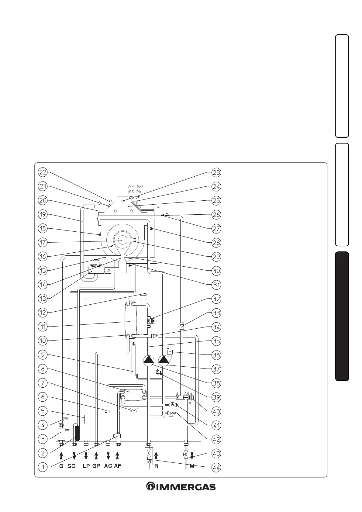
3.1 HYDRAULIC DIAGRAM.
Key:
1 - DHW ow switch
2 - Condensate drain trap
3 - Gas valve
4 - Gas valve outlet pressure point (P3)
5 - Liquid phase detection probe
6 - DHW probe
7 - System lling cock
9 - System expansion vessel
8 - DHW heat exchanger
10 - Heat pump ow probe
11 - Water - gas plate exchanger
12 - Air vent valve
13 - Fan
14 - Air/gas Venturi manifold
15 - Gas nozzle
16 - Detection electrode
17 - Burner
18 - Flue gas thermofuse
19 - Air intake pipe
20 - Manual air vent valve
21 - Heat exchanger safety thermofuse
22 - Air sample point
23 - Flue sample point
24 - ∆P gas pressure point
25 - Fumes hood
26 - Safety thermostat
27 - Heat generator ow probe
28 - Heat generator return probe
29 - Ignition electrodes
30 - Venturi negative signal (P2)
31 - Venturi positive signal (P1)
32 - System ow-meter
33 - One-way valve
34 - One-way valve
35 - Heat pump return probe
36 - Air vent valve
37 - Heat generator circuit circulator
38 - Heat pump circuit circulator
39 - System pressure switch
40 - Heat generator 3-way valve
41 - System draining cock
42 - 3 bar safety valve
43 - System interception cock
44 - System interception cock
G - Gas supply
SC - Condensate drain
LP - Chiller line - liquid phase
GP - Chiller line - gaseous phase
AC - domestic hot water outlet
AF - Domestic cold water inlet
R - System return
M - System ow