30
INSTALLERUSERMAINTENANCE TECHNICIAN
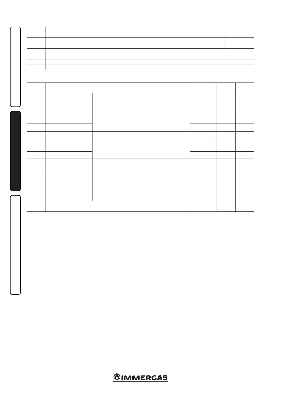
Id
Parameter
Description Range Default
Value
range
U 01 Zone 2 heating setting
Zone 2 heating ow set point in case of no thermal regulation
("R 01" = OFF). If CARV2 is present in zone 2 only, then the
parameter will be used to set the zone 1 set point.
25 ÷ 80 °C 25
U 02 Zone 2 cooling setting
Zone 2 cooling ow set point in case of no thermal regulation
("R 01" = OFF).
7 ÷ 25 °C 20
U 03 Zone 1 central heating oset
You can edit the ow temperature with respect to the external
probe regulation curve in central heating mode (Fig. 8 value
Oset)
- 15 ÷ + 15 °C 0
U 04 Zone 2 central heating oset - 15 ÷ + 15 °C 0
U 05 Zone 1 cooling oset
You can edit the ow temperature with respect to the external
probe regulation curve in cooling mode (Fig. 8 value Oset)
- 15 ÷ + 15 °C 0
U 06 Zone 2 cooling oset - 15 ÷ + 15 °C 0
U 07 Zone 1 humidity setting
e humidity temperature sensor (optional) denes room hu-
midity in the corresponding area
30 ÷ 70 % 50
U 08 Zone 2 humidity setting 30 ÷ 70 % 50
U 09 Zone 1 cooling setting
Zone 1 cooling ow set point in case of no thermal regulation
("R 01" = OFF). Use it if CAR
V2
present
7 ÷ 25 °C 20
U 11 Night function
is function can only be activated if CAR
V2
(optional) is available
Activating the function allows you to reduce the compressor
frequency during the condensing unit operation in the time slot
set in the U 12 and U 13 parameters.
Make sure the additional power sources needed to meet potential
requirements that may present themselves during active opera-
tion are available (e.g. additional resistances)
OFF - ON OFF
U 12 Night function enabling time 0 ÷ 23 0
U 13 Night function disabling time 0 ÷ 23 0
N.B.: the parameters referring to zone 2 can only be displayed if there is a zone 2 on the system and it is congured correctly.
User Menu.
D 78 4-way side (CL = cooling, HT = heating) HT / CL
D 79 Temperature detected by the condensing unit external probe -55 ÷ +45 °C
D 80 Heat pump status (reserved to Technical Assistance Service) 0 ÷ 8
D 91 Main board soware version
D 92 Ignition board soware version
D 97 Heat pump request state (reserved to Technical Assistance Service) 0 ÷ 999
D 98 Heat generator request state (reserved to Technical Assistance Service) 0 ÷ 999
D 99 System state (reserved to Technical Assistance Service) 0 ÷ 999
2.7 INDOOR UNIT SHUTDOWN.
Switch the indoor unit o by putting it in “o”
mode, disconnect the onmipolar switch out-
side of the indoor unit and close the gas cock
upstream from the appliance. Never leave the
indoor unit switched on if le unused for pro-
longed periods.
2.8 RESTORE CENTRAL HEATING
SYSTEM PRESSURE
Periodically check the system water pressure. e
indoor unit pressure gauge must show a value
between 1 and 1.2 bar.
If the pressure is less than 1 bar (with the system
cold), you must restore it using the cock located at
the bottom of the unit (Fig. 3).
N.B.: close the valve aer the operation.
If pressure values reach around 3 bar the safety
valve may be activated.
In this case, remove water from a radiator air
vent valve until a pressure of 1 bar is achieved,
or ask for assistance from professionally qualied
personnel.
In the event of frequent pressure drops, contact
qualified staff for assistance to eliminate the
possible system leakage.
2.9 DRAINING THE SYSTEM.
To drain the indoor unit, use the special draining
valve (Fig. 3).
Before draining, ensure that the lling cock is
closed.
2.10 ANTIFREEZE PROTECTION.
e indoor unit has an antifreeze function of
the heat pump circulator that switches on when
the water temperature drops below 8 °C. e
indoor unit has a further anti-freeze function that
automatically switches on the heat generator or
operation in heat pump mode when the tempera-
ture drops below 4°C (standard protection up to a
minimum temperature of -5 ° C). All information
relative to the anti-freeze protection is stated
in par. 1.3. In order to guarantee the integrity
of the appliance and the domestic hot water
heating system in areas where the temperature
drops below zero, we recommend protecting the
central heating system using anti-freeze liquid
and installing the Immergas Anti-freeze Kit in
the hydronic module. In the case of prolonged
inactivity (second case), we also recommend that:
- the electric power supply is disconnected;
- completely empty the central heating circuit
and the indoor unit domestic hot water circuit.
In systems that are drained frequently, lling
must be carried out with suitably treated water
to eliminate hardness that can cause lime-scale.
2.11 CASE CLEANING.
Use damp cloths and neutral detergent to clean
the indoor unit casing. Never use abrasive or
powder detergents.
2.12 DECOMMISSIONING.
In the event of permanent shutdown of the
indoor unit, contact professional sta for the pro-
cedures and ensure that the electrical, water and
gas supply lines are shut o and disconnected.

 Loading...


