46
42
INSTALLERUSERMAINTENANCE TECHNICIAN
3.18 DIVERTER VALVE MANAGEMENT
SUMMER / WINTER.
e unit electronics has a 230V outlet to manage
the summer / winter diverter valves. e switch
occurs when the mode (summer / winter) is
changed from the control panel or from the
CAR
V2
.
3.19 AUTOMATIC VENT FUNCTION.
In the case of new central heating systems and
in particular mode for oor systems, it is very
important that deaeration is performed correctly.
e function consists of the cyclic activation of
the pump and the 3-way valve.
e function is activated in two dierent ways:
- each time the heat generator is re-powered;
- using parameter "M01".
N.B.: if the indoor unit is connected to the
CAR
V2
the “stand-by” function can only be
activated via the remote control panel.
In the rst case, the function has a duration of
8 minutes and it can be interrupted by pressing
the “reset” button (3). In the second case, it has
a duration of 18 hours and it can be interrupted
simply by switching the heat generator on.
Activation of the function is signalled by the
countdown shown on the indicator (14).
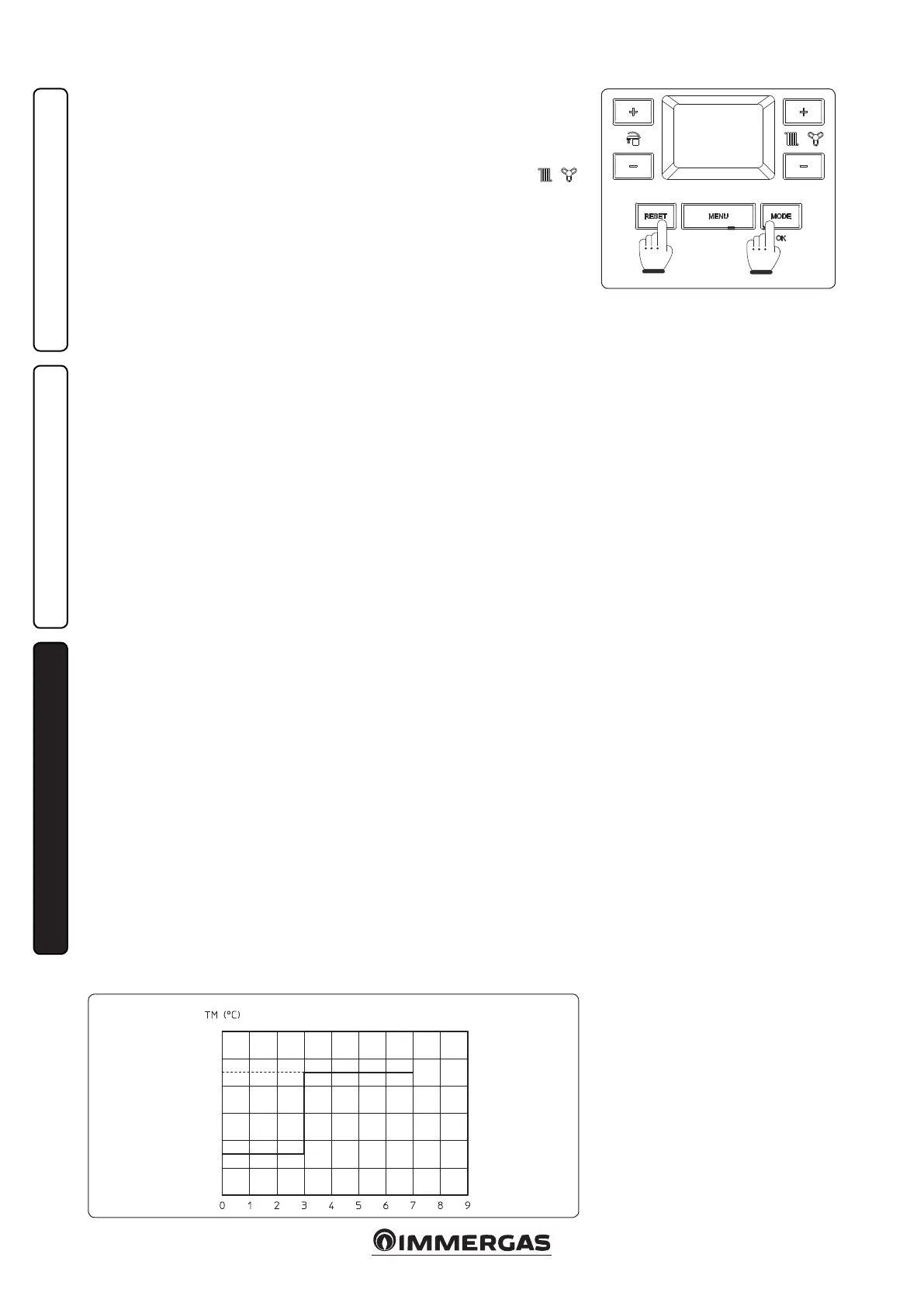
3.20 SCREED HEATER FUNCTION.
e indoor unit is equipped with a function to
perform the thermal shock on new radiant panel
systems, as required by the applicable standard.
Attention: contact the manufacturer of the radi-
ant panels for the thermal shock characteristics
and its correct execution.
N.B.: to be able to activate the function, no re-
mote control must be connected and the system
divided into zones must be properly connected,
both hydraulically and electrically.
e active zone pumps are those with ongoing
requests, made via the room thermostat input.
e function is activated from indoor unit in
stand-by by pressing and holding the buttons
“Reset” and “Mode” for more than 5 seconds
(Fig. 45).
e function lasts in total 7 days - 3 days at the
lowest temperature set and 4 days at the high-
est temperature set (Fig. 46). Duration can be
changed by changing the value of parameters "T
22" and "T24".
Aer activating the function, the lower set (range
20 ÷ 45 °C default = 25 °C) and the higher set
(range 25 ÷ 55 °C default = 45 °C) appear in
sequence.
The temperature is selected by means of the
buttons “+” and “-” of the system side (
) and conrmed by pressing the button “Mode”.
e display now shows the countdown of days
alternated with the current ow temperature,
as well as the normal operating symbols of the
indoor unit.
In case of failure, the function is suspended and
will resume when normal operating conditions
are reset from the point where it was inter-
rupted. In case of power failure, the function
is suspended.
When the time expires, the indoor unit auto-
matically goes back to “Stand-by” mode, the
function can also be stopped by pressing the
button “Mode”.
3.21 SOLAR PANELS COUPLING
FUNCTION
e indoor unit is prepared to receive pre-heat-
ed water from a system of solar panels up to a
maximum temperature of 65°C. In any case, it
is always necessary to install a mixing valve on
the hydraulic circuit upstream of the indoor unit,
on the cold water inlet.
To optimise operation, where the probe is not
already tted on the indoor unit, the solar inlet
probe kit is available on request (see wiring
diagram Fig. 5):
- if there is no probe kit, it is advisable to set
parameter A6 (DHW thermostat) at “1”;
- otherwise, where the kit is installed or the
probe is already tted in the indoor unit, pa-
rameter A6 must be le at “0”. is kit allows
you to connect a probe on the domestic cold
water inlet pipe of the indoor unit, to prevent
unnecessary start-ups in systems with water
heating through solar systems or alternative
sources. e indoor unit will not turn on if the
inlet water is suciently hot.
In both conditions (probe present or not), we
recommend setting parameter t3 (solar delay
timing) at a time sucient to let the water in-
side the D.H.W. circuit upstream of the indoor
unit drain.
e greater the distance from the storage tank,
the longer wait time will have to be set.
45
With these adjustments made, when a domestic
withdrawal is requested, once the time set on
parameter “t3” has passed, if the water entering
the indoor unit is at a temperature that is equal
or greater to that set, the indoor unit will not
turn on.
Note: in order for the indoor unit to work prop-
erly, the temperature selected on the mixing valve
must be 5°C higher than the temperature selected
on the indoor unit control panel.
3.22 DEHUMIDIFICATION FUNCTION
Dehumidication can be performed according
to two dierent types of devices:
1) humidistat;
2) humidity sensor.
In the rst case, the cooling mode temperature
corresponds to:
- in the event of dehumidication request: ma-
ximum setpoint set for the request zone;
- in the event of dehumidication and cooling
request: setpoint set for the request zone.
In the second case, the cooling mode temperature
corresponds to:
- in the event of dehumidication request: ma-
ximum setpoint set for the request zone;
- in the event of dehumidication request and
cooling request: setpoint set for the request
zone, but limited by the calculated dew tem-
perature.
e dew temperature is only calculated for
adjustments above or equal to 15°C.
3.23 AUDAX PRO TESTMODE
FUNCTION
In the event of using the functions:
- test function;
- pump down (see Audax Pro instruction ma-
nual);
the indoor unit must be set in "Stand-by" mode.
UPPER
SET
LOWER
SET
DAYS

 Loading...


