1
Per il sollevamento dello scambiatore di calore, attenersi alle
seguenti linee guida:
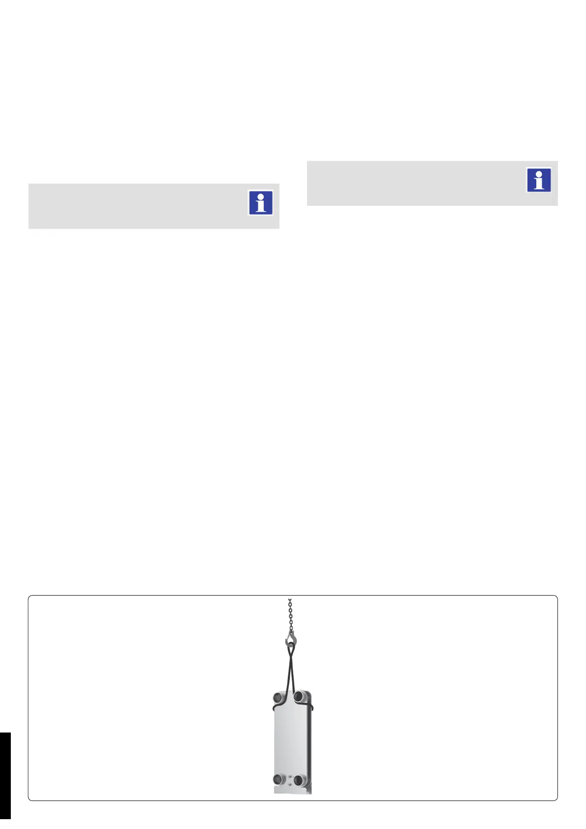
1. Posizionare le cinghie come mostrato in g. 1.
2. Sollevamento in posizione verticale.
3. Abbassare lentamente lo scambiatore di calore in posizione
verticale.
4. Rimuovere le cinghie.
Installazione.
Di norma, lo scambiatore deve essere installato in modo che i
ussi di uido attraverso di esso procedano in direzione opposta.
Collegare lo scambiatore saldobrasato a piastre.
Tutti i dispositivi di sicurezza necessari per la regola-
zione dei recipienti a pressione devono essere installati
di conseguenza.
Una volta collegato il sistema di tubazioni allo scambiatore, assi-
curarsi che non vengano trasferiti carichi (compresi gli eetti di
coppia) dal sistema di tubazioni allo scambiatore di calore.
Quando il sistema di tubazioni è collegato allo scambiatore di
calore, è necessario isolarlo da pulsazioni di pressione, vibrazioni
e shock termici.
Per sostenere lo scambiatore, utilizzare staffe di montaggio
installate alla base dello scambiatore di calore. Lo scambiatore
non è stato progettato per resistere a forze eccessive, per esempio
generate da terremoti, vento, incendi, vibrazioni, supporto assente
o insuciente, tubazioni, ecc.
È responsabilità del progettista dell'impianto o dell'utente nale
proteggere lo scambiatore di calore e ridurre il rischio di danni.
È necessario installare una valvola di sicurezza fra lo scambiatore
di calore e le valvole di intercettazione sul lato secondario dello
scambiatore.
Se non si installa una valvola di sicurezza, la dilatazione termica
del uido potrebbe danneggiare gravemente lo scambiatore alla
chiusura delle valvole di intercettazione.
Le tubazioni devono essere collegate in modo da evitare che le
sollecitazioni da esse generate (ad es. dilatazione termica) dan-
neggino lo scambiatore.
Al ne di prevenire possibili sollecitazioni di torsione sui raccordi
dello scambiatore, le tubazioni devono essere dotate di apposite stae.
I carichi di collegamento massimi consentiti sono indicati nella
tabella di seguito.
Sollevamento / Liing
Please follow below guideline for liing the heat exchanger:
1. Place straps as shown on the Fig. 1.
2. Liing in vertical position.
3. Lower the heat exchanger slowly to vertical position.
4. Remove the straps.
Installation.
In general, the plate exchanger is installed so that ows of the
media through it is in opposite direction.
Connecting the Brazed plate heat exchanger.
All safety equipment which is required by pressure
vessel regulation must be installed accordingly.
When the pipe system is connected with the plate exchanger make
sure that no loads from piping (including torque eects) are tran-
sferred fromthe piping system to the heat exchanger.
e pipe system should be isolated against pressure pulsations,
vibrations and any thermal shock when connected to the heat
exchanger.
To support the plate heat exchanger, it is advisable to use a
mounting bracket tted at the bottom of the heat exchanger. e
plate heat exchanger has not been designed to withstand excessive
forces from earthquake, wind, re, vibration, missing or failing
support, excessive forces from the piping etc.
It is the system designer or end user’s responsibility to protect the
plate heat exchanger and reduce the damage risk.
A safety valve should be installed between the heat exchanger
and the shut-o valves on the secondary side of the plate heat
exchanger.
If the safety valve is not installed, thermal expansion of uid
might destroy the plate heat exchanger when the shut-o valves
are closed.
e pipes must be connected in the way that the stress caused
by them (e.g., thermal expansion), does not harm the plate heat
exchanger.
e pipes should be equipped with brackets to prevent any torsion
stress to be concentrated at the heat exchanger’s pipe connections.
e maximum allowable connection loads given in the table below.
STD.010398/000
 Loading...