ASSEMBLY INSTRUCTION
Tools Required to Assemble the Machine: Two Adjustable Wrenches and Allen Wrenches
NOTE: It is strongly recommended this machine be assembled by two or more people to
avoid possible injury.
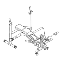
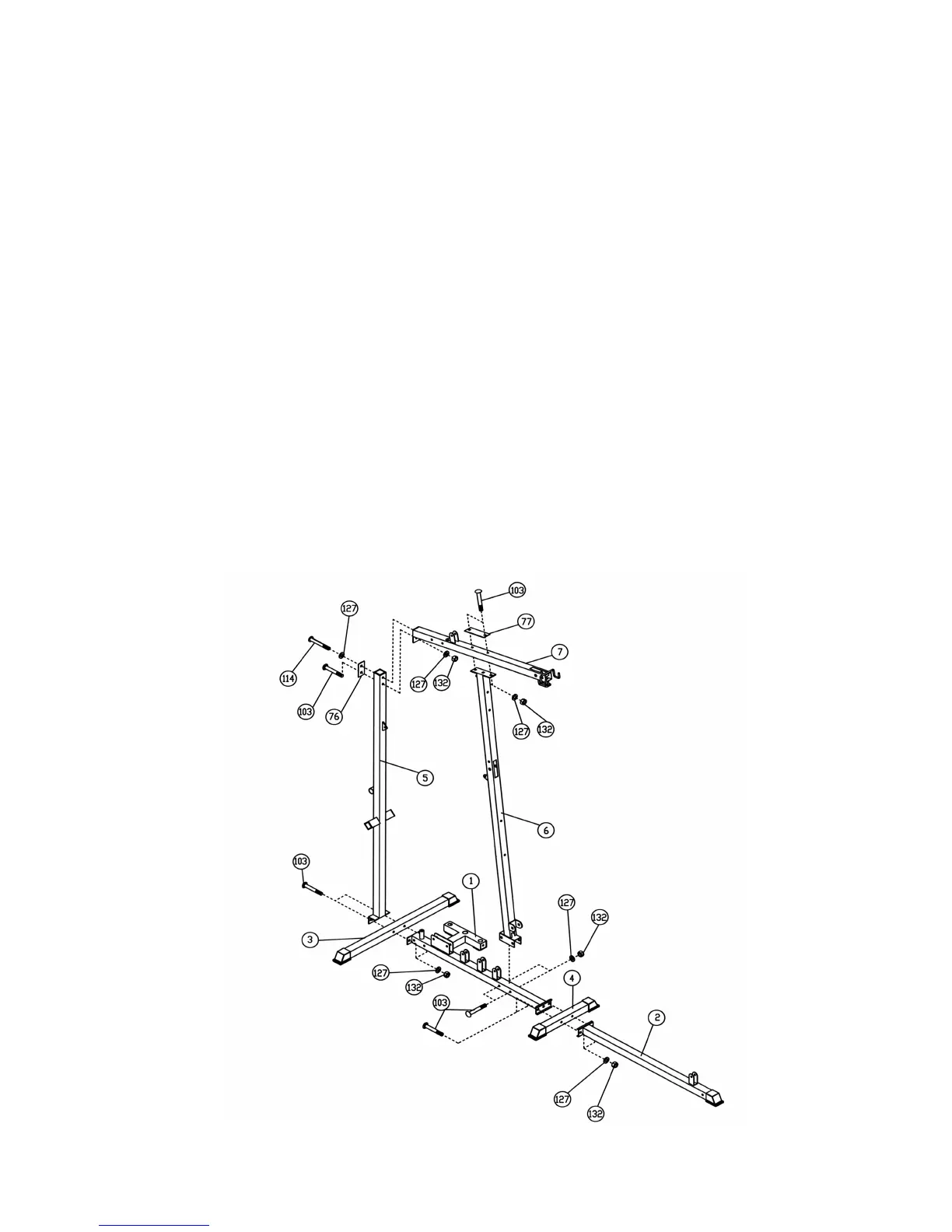
STEP 1 (See Diagram 1)
A.) Place the Main Base Frame (#1), Front Stabilizer (#4) and Front Base Frame (#2) on the floor.
Secure the three pieces together with two M10 x 2 ¾” Carriage Bolts (#103), ∅3/4” Washers
(#127), and M10 Aircraft Nuts (#132). DO NOT tighten all the nuts and bolts yet.
B.) Attach the Rear Stabilizer (#3) and Rear Vertical Beam (#5) to the back end of the Main Base
Frame (#1). Secure it with two M10 x 2 ¾” Carriage Bolts (#103), ∅3/4” Washers (#127), and
M10 Aircraft Nuts (#132).
C.) Attach the Front Vertical Beam (#6) to the Main Base Frame (#1). Secure it with two M10 x 2
¾” Carriage Bolts (#103), ∅3/4” Washers (#127), and M10 Aircraft Nuts (#132).
D.) Attach the Upper Frame (#7) to the Rear Vertical Beam (#5). Secure the top hole with one 4”
x 2” Bracket (#76), ∅3/4” Washer (#127), and M10 x 2 ½” Allen Bolt (#114). Secure the
bottom hole with one M10 x 2 ¾” Carriage Bolt (#103), ∅3/4” Washer (#127) and M10 Aircraft
Nut (#132).
E.) Attach the Upper Frame (#7) to the top of the Front Vertical Beam (#6). Secure it with two
M10 x 2 ¾” Carriage Bolts (#103), one 6 ¼” x 2” Bracket (#77), two ∅3/4” Washers (#127)
and M10 Aircraft Nuts (#132).
DIAGRAM 1
4
STEP 2 (See Diagram 2)