ASSEMBLY INSTRUCTION
Tools Required to Assemble the Machine: Two Adjustable Wrenches and Allen Wrenches
NOTE: It is strongly recommended this machine to be assembled by two or more people to
avoid possible injury.
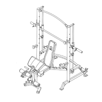
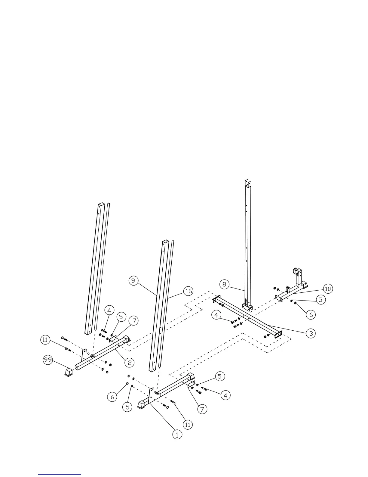
STEP 1 (See Diagram 1)
A.) Connect the Main Base Frame (#3) to both Left & Right Base Frames (#1) & (#2). Secure
them with one Bracket (#7), two M10 x 3” Allen Bolt (#4), four ∅ ¾” Washers (#5), and two
M10 Aircraft Nuts (#6) on each end of the Main Base Frame.
B.) Attach one Front Vertical Beam (#9) to Left Base Frame (#1). Secure it with two M10 x 2 ¾”
Carriage Bolts (#11), ∅ ¾” Washers (#5), and M10 Aircraft Nuts (#6). Repeat the same
procedure to install the other Vertical Beam to the Right Base Frame (#2). Insert the Guide
Rods (#16) into the hole on the Left & Right Base Frame. Secure them with two M8 x 3/8”
Allen Set Screws (#60).
C.) Attach the Middle Vertical Beam (#8) to the Main Base Frame (#3). Attach the Rear Stabilizer
(#10) to the rear of the Main Base Frame (#3). Secure them all together with two M10 x 3”
Allen Bolts (#4), four ∅ ¾” Washers (#5), and two M10 Aircraft Nuts (#6).
4
 Loading...