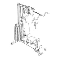
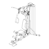
STEP 2 (See Diagram 2)
A.) Do not tighten all Nuts and Bolts until instructed to do so.
B.) Align the holes on the Upper Frame (#1) with the top of the Guide Rods (#11). Place the
Upper Frame onto the Vertical Frame (#4).
C.) Secure the Upper Frame to the Guide Rods with two M10 x 1” Allen Bolts (#64) and Ø ¾”
Washers (#73).
D.) Secure the Upper Frame to the Vertical Frame with two M10 x 2 3/8” Carriage Bolts (#58),
one 1 ¾” x 4 ¾” Bracket (#18), two ¾” Washers (#73), and two M10 Aircraft Nuts (#70).
E.) Securely tighten all Nuts and Bolts previously installed in Step-1 and Step-2.
F.) Attach the Leg Developer (#7) to the open bracket on Seat Support (#5). Secure it with one
Leg Developer Axle (#67), two M10 x 1” Allen Bolts (#64), and two Ø ¾” Washers (#73).
G.) Attach Seat Pad (#23) to Seat Support. Secure it with four M8 x 5/8” Allen Bolts (#60) and
four Ø 5/8” Washers (#72).
H.) Attach Backrest Board (#24) to Vertical Frame. Secure it with two M8 x 2 1/8” Allen Bolts
(#63) and two Ø 5/8” Washers (#72).
8
 Loading...