FUSE
ON
PROT
B+GND REM
LEFT RIGHT
BRIDGED
POWER SPEAKER
FUSE
ON
PROT
B+GND REM
LEFT RIGHT
BRIDGED
POWER SPEAKER
FUSE
ON
PROT
B+GND REM
LEFT RIGHT
BRIDGED
POWER SPEAKER
FIG.3
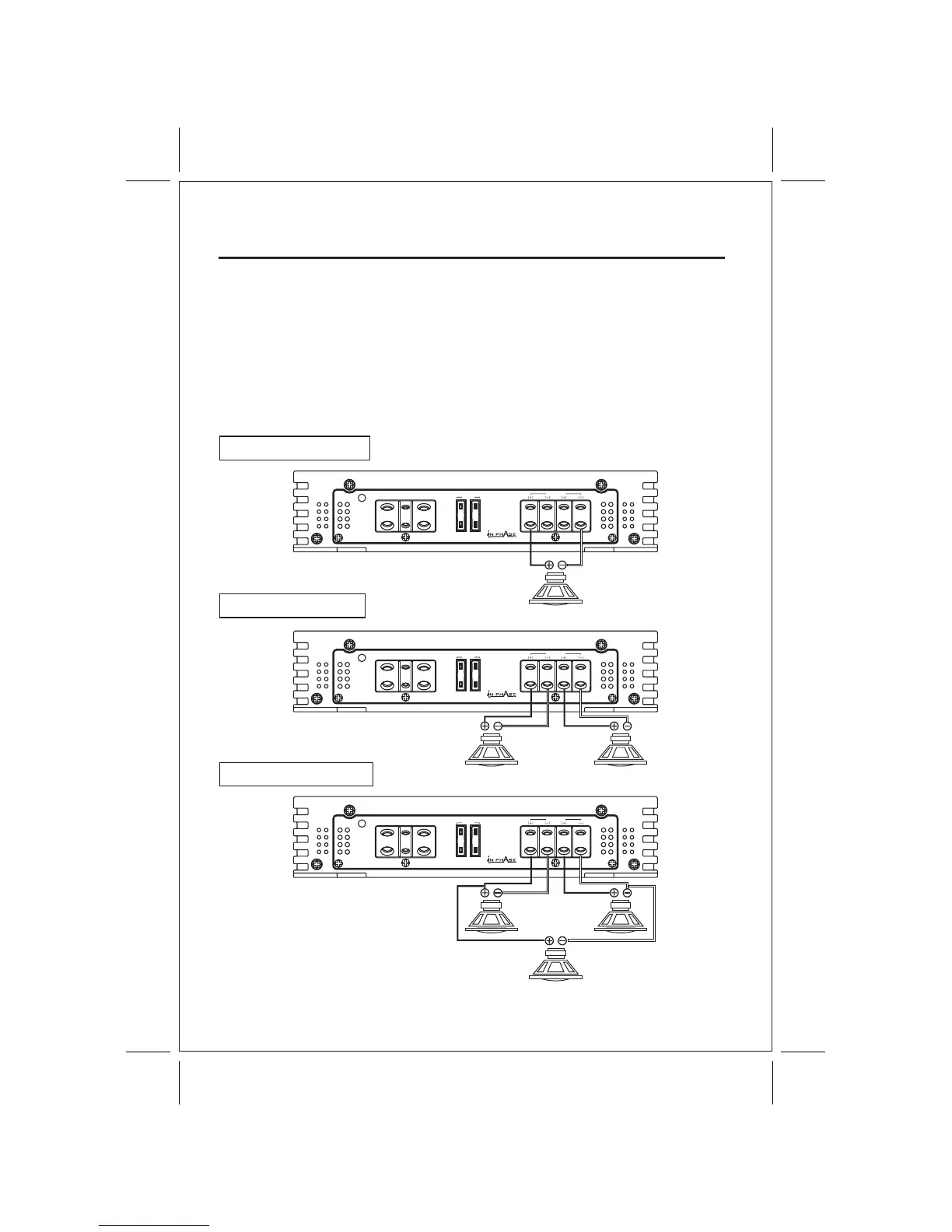
This amplifier can operate in one, two or three channel mode. The minimum impedance for
single channel (bridged/mono) operation is 4 or 8 ohms. Tri channel power is referred to
stereo and mono at the same time. Minimum impedance remains the same for three channel
(front /subwoofer) systems as long as proper passive crossovers are used. Connect right
and left speaker wire to corresponding speaker output terminals of the amplifier. Be sure to
have the positive wire from the speaker connected to the positive speaker terminal of the
amplifier and the negative wire from the speaker must connect with the negative speaker
terminal of the amplifier. Reversing any of these connections will result in the speaker cones
moving out of phase which causes bass cancellation. See Fig.3 Speaker Output Connections.
SPEAKER CONNECTIONS
2 CHANNEL SPEAKER WIRING DIAGRAM
9
1 SPEAKER BRIDGED
2 SPEAKER STEREO
3 SPEAKER TRI MODE
4 - 8 Ohm
1CH
2 - 4 Ohm
1 CH
2 CH
WOOFER 2CH+1CH
4 - 8 Ohm
2 CH
3 CH
1 CH
4 - 8 Ohm