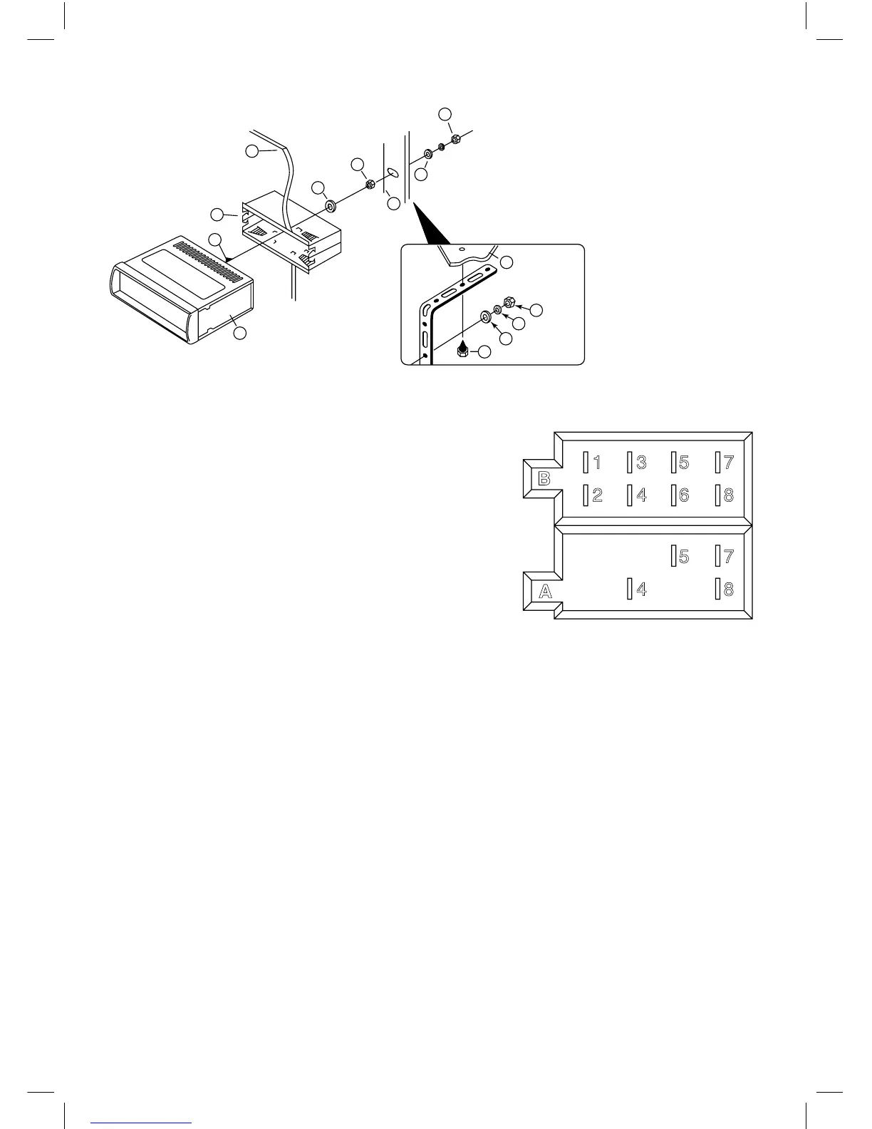
TO SUPPORT THE UNIT
ISO CONNECTOR
RCA Jack Line Out: Red (right) White (left)
RCA Jack Line In: Red (right) White (left)
CONNECTOR A
1.
2.
3.
4. MEMORY +12V
5. AUTO ANTENNA OUTPUT
6.
7. +12V (TO IGNITION KEY)
8. GROUND
Note: (connector A no. 7) must be connected by car ignition key in order to avoid that car bat-
tery being drained when the car will be not used for long period.
CONNECTOR B
1. REAR RIGHT SPEAKER (+)
2. REAR RIGHT SPEAKER (-)
3. FRONT RIGHT SPEAKER (+)
4. FRONT RIGHT SPEAKER (-)
5. FRONT LEFT SPEAKER (+)
6. FRONT LEFT SPEAKER (-)
7. REAR LEFT SPEAKER (+)
8. REAR LEFT SPEAKER (-)
Maintenance
FUSE REPLACEMENT
If the fuse blows, check the power connection and replace the fuse. If the fuse blows again
after the replacement, there may be an internal malfunction. In this case, consult your nearest
repair center.
Warning
Use the specified amperage fuse for each lead. Use of a higher amperage fuse may cause
serious damage.
1. UNIT
2. RELEASE CASE
3. DASH BOARD
4. HEX NUT
5. LOCK WASHER
6. PLAIN WASHER
7. CAR BODY
8. REAR SUPPORT STRAP
9. TAPPING SCREW
10. M5 X 15 HEX BOLT
Dashboard