INCOE
®
I Series IC-15A Temperature Control Module
Quick Start Manual
Page 2 of 5 12/02/2013
INCOE
®
Corp. Global Headquarters 1740 E. Maple Road Troy, Mi 48083 USA T: 248-616-0220 E: tech.support@incoe.com www.incoe.com
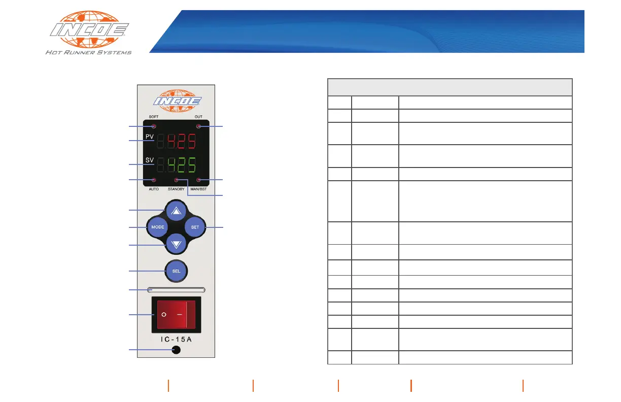
MODULE INTERFACE
1 2
6
7
11
3
8
10
9
12
13
14
15
4
5
Interface Features
1 SOFT LED Indicates module in Soft Start phase
2 OUT LED Indicates power output from module
3 PV Display
Displays Present Value (PV) of measured
temperature (red four digit display)
4 SV Display
Displays Set Value (SV) for temperature
(green four digit display)
5 AUTO LED
Indicates module in Automatic Operation
6
MAN/BST
LED
Blink - Indicates module in Manual
Operation
ON - Indicates module utilizing
Boost feature
7
STANDBY
LED
Indicates module utilizing Standby feature
8
▲
Value increase button
9
▼
Value decrease button
10
MODE
MODE button
11
SET
SET button
12
SEL
SEL button
13 Handle
14
On/Off
Switch
15 Lock Pin
 Loading...