25
Data Block = Begins with the number of the first register (two bytes) in a command packet,
or data from the first register (two bytes) in a response packet. Followed by the number of
registers to be read (two bytes) in a command packet, or by data from subsequent registers.
Last 2 Bytes = Error Checking CRC – Lo Byte & Hi Byte
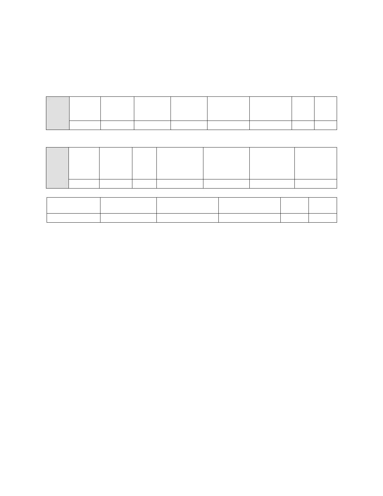
Table 3.3 Read Registers Command Format
3.5.2 RS-485 Packet Format - Write
Write to Holding Registers:
GAP = A gap in transmission of 3.5 character frames indicates to the slaves that a new packet
is to follow. No transmission gaps within a packet may exceed 1.5 character frames.
Byte 1 = Device Address: Address 0 is a broadcast address that all units respond to regardless
of programmed address. All other addresses can be programmed and used in this mode.
Byte 2 = Function Code: When writing to holding registers, this byte is “10h”
Data Block = Begins with the number of the first register to be written (two bytes), followed
by the number of registers to be written (two bytes), in either command or response packets.
In a command packet the programming data for the first register will be the next two bytes
followed by programming data for subsequent registers.
Last 2 Bytes = Error Checking CRC – Lo Byte & Hi Byte