6
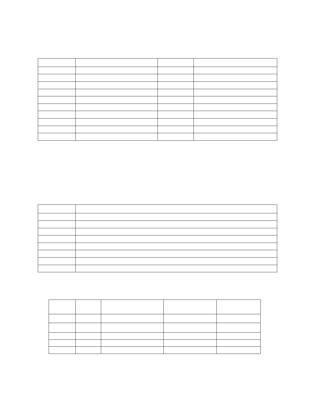
Table 1.1 Terminal Functions
A DIP switch tells the firmware which hardware options are installed, so their function can be
enabled. It is located on the top PCB, above the power transformer and is accessible through
a slot in the left side of the case, towards the rear of the instrument.
Table 1.2 DIP Switch Functions
ASCII Communication Protocol Enable
MODBUS Communication Protocol Enable
High / Low Relay Limit Option Enable
Analog Output Option Enable
Table 1.3 Digital Communication Connector Pin-Out
RS-485 Comm
Port Adapter Pin #