EasyManua.ls Logo

Incra TS-LS User Manual

Default Icon
12 pages
To Next Page IconTo Next Page
Page #1 background imageLoading...
Page #1 background image
INCRA
The only table saw
fence with patented
Automatic Lead Screw
Positioning Control
TM
Safety . . . . . . . . . . . . . . . . . . . . 2
Fasteners and Hardware Lists. . . . 2
Rail Assembly . . . . . . . . . . . . . . 4
Base Mount Assembly . . . . . . . . . 6
Fence Assembly . . . . . . . . . . . . . 8
Final Calibration. . . . . . . . . . . . . . 9
Blade Guard Adjustments . . . . . . 11
Extension Table . . . . . . . . . . . . . 11
Auxiliary Fence Mounting . . . . . . 12
Maintenance . . . . . . . . . . . . . . . 12
Warranty . . . . . . . . . . . . . . . . . . 12
CONTENTS
Please read this owners manual and
keep it at hand for reference.
Note: The INCRA TS-LS system consists of
three packages. One of the packages contains
the rails and another, the base mount unit.
These two assemblies are covered fully by this
owner’s manual. The third package contains
the INCRA LS Positioner. Read all of this
TS-LS owner’s manual and the Safety, Getting
Acquainted and Operations sections of the
LS Positioner manual. If you have also pur-
chased one of the router table extension wings,
complete all assembly instructions in
this manual BEFORE attaching the
router table.
In just about an hour or so, you
are going to be operating one
of the most exciting new tools in
today’s woodshops. Your table
saw will undergo a transforma-
tion, and what was once an
average saw will emerge a preci-
sion woodworking machine, one you’ll be proud
of for years to come. So take a few minutes to
read over the safety information and mounting
instructions, then grab a Phillips screwdriver
and a set of wrenches and let’s get started
.
OWNER’S MANUAL
Question and Answer IconNeed help?

Do you have a question about the Incra TS-LS and is the answer not in the manual?

Incra TS-LS Specifications

General IconGeneral
BrandIncra
ModelTS-LS
CategorySaw
LanguageEnglish

Summary

Safety Instructions

Important Safety Precautions for INCRA TS-LS

Key safety precautions for operating the INCRA TS-LS system.

Fasteners and Hardware Packs

Mounting Bracket Hardware Pack B-01

Details of hardware included in the Mounting Bracket Hardware Pack B-01.

Rail Hardware Pack B-02

List and description of fasteners in Rail Hardware Pack B-02.

Base Mount and Fence Glide Hardware Pack B-03

List and description of fasteners for base mount and fence glide.

LS Mounting Hardware Pack B-04

List and description of fasteners for LS Positioner Base mounting.

Rail Assembly

Attach Mounting Brackets

Instructions for attaching mounting brackets to the table saw.

Loosely Attach Rail Bolts

Connecting rail bolts to the mounting brackets.

Slide Rails onto Mounting Brackets and Tighten Bolts

Securing the rails to the mounting brackets.

Set Final Mounting Bracket Position

Adjusting Mounting Bracket Position

Setting the final position of mounting brackets using base clamps.

Set Final Rail Position

Positioning and Tightening Rails

Positioning and tightening the rails on the mounting brackets.

Custom Setups

Customizing Rail Placement

Guidance on adjusting rail positions for custom setups.

Install Stop Positioners and Base Clamping Knobs

Attaching Stop Positioners and Knobs

Attaching stop positioners and base clamping knobs to the rails.

Base Mount Assembly

Attach Glide Pads to Base Clamps

Applying glide pads to the underside of base clamps.

Remove Endcaps from Base Support Panel

Removing end caps from the base support panel.

Attach Base Clamp to Support Panel

Securing a base clamp to the base support panel.

Attach LS Positioner Base to Support Panel

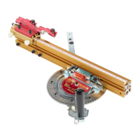
Mounting the LS Positioner Base onto the support panel.

Align Base Mount Assembly Parallel to Miter Slot

Aligning Base Mount to Miter Slot

Ensuring the base mount assembly is parallel to the table saw's miter slot.

Set Final Base Assembly Position

Final Positioning of Base Assembly

Final positioning of the base assembly on the rails.

Fence Assembly

Slide Carriage into LS Positioner Base

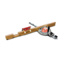
Inserting the LS carriage into the LS Base.

Loosely Attach TS-LS Fence

Initial attachment of the TS-LS fence to the mounting bracket.

Attach Fence Glides

Installing the fence glides onto the rear of the fence.

Tighten Fence Mounting Screws

Securing the fence mounting screws properly.

Engage Anti-Lift Rail Hooks

Activating the rail hooks to prevent fence lift.

Final Calibration

Align Fence Parallel to Miter Slot

Aligning fence parallel to miter slot and tightening LS Base screws.

Zero Fence to Saw Blade

Setting the fence to zero relative to the saw blade.

Set Scale Position

Positioning the scale to the zero mark.

Calibration - Left Side of Saw Blade

Reverse LS Position to Left End of Rails

Reversing LS position and sliding to the left end of rails.

Align Fence Parallel to Miter Slot

Aligning fence parallel to miter slot and tightening clamp screws.

Zero Fence to Left of Saw Blade

Setting fence to zero on the left side of the saw blade.

Set Scale and Stop Positions

Setting the scale and stop positions for left-side calibration.

Blade Guard Adjustments

Rear Rail Modification

Modifying the rear rail for proper blade guard clearance.

Extension Table

Attaching Table Board Support

Instructions for creating and attaching table board supports.

Auxiliary Fence Mounting

Mounting Wooden Auxiliary Fence

Mounting a wooden auxiliary fence to the TS-LS fence.

Floating Stops

Installing Floating Stops on Rails

Guidance on installing floating stops for mid-range positioning.

Maintenance

Cleaning and Lubrication

Instructions for cleaning and lubricating the TS-LS for optimal performance.

Warranty

Warranty Information and Terms

Details regarding the product warranty and claims process.

Related product manuals