10
GB
Installation
Assembly
Remove the metal grille before beginning assembly,
this will make it easier to manoeuvre the apparatus
(see section “cleaning the grease filters” section in the
“Maintenance” chapter for instructions).
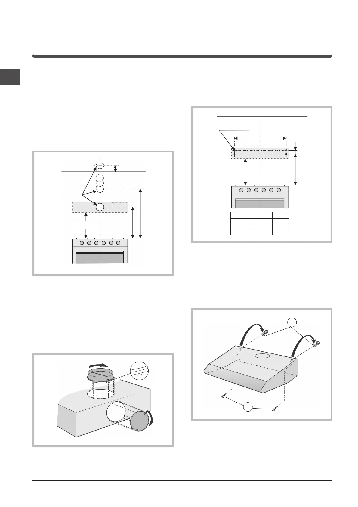
1) Drill a hole in the wall for an air outlet (with a
diameter of 133mm) as per the Diagram below
which shows the measurements for the various
possible situations.
2) Some models are fitted with an upper air vent (B)
and a rear air vent (A) closed by a plate that must
be removed if you wish to use it. Fit the flange (C)
on the vent used; if you use the rear vent, close the
upper one with the cap (E) to be ordered from your
dealer.
Some models are fitted with 2 air vents, one in the
upper part (B) and one at the rear (A), which you
can use as required. Fit the flange (C) on the vent
used and close the other one with the cap (E).
85
Ø133
720
min
940
min650
C
E
B
A
3) Wall mounting
a) Make 4 holes in the wall following the
measurements shown in the diagram below and
insert the plugs.
b) Take 2 of the supplied screws (G) and insert
them into the plugs without tightening them
completely.
c) Hang the hood onto the 2 screws and tighten the
2 screws to the wall working from inside the
apparatus.
d) Complete final fixing by inserting the other 2
screws (H).
Ø 8mm
A
44
732
min650
=
=
MODELS A X
50cm 44cm 41cm
60cm 54cm 51cm
90cm 84cm 81cm
G
H
 Loading...