26 of 37
Service Manual UK
Indesit
Company
English
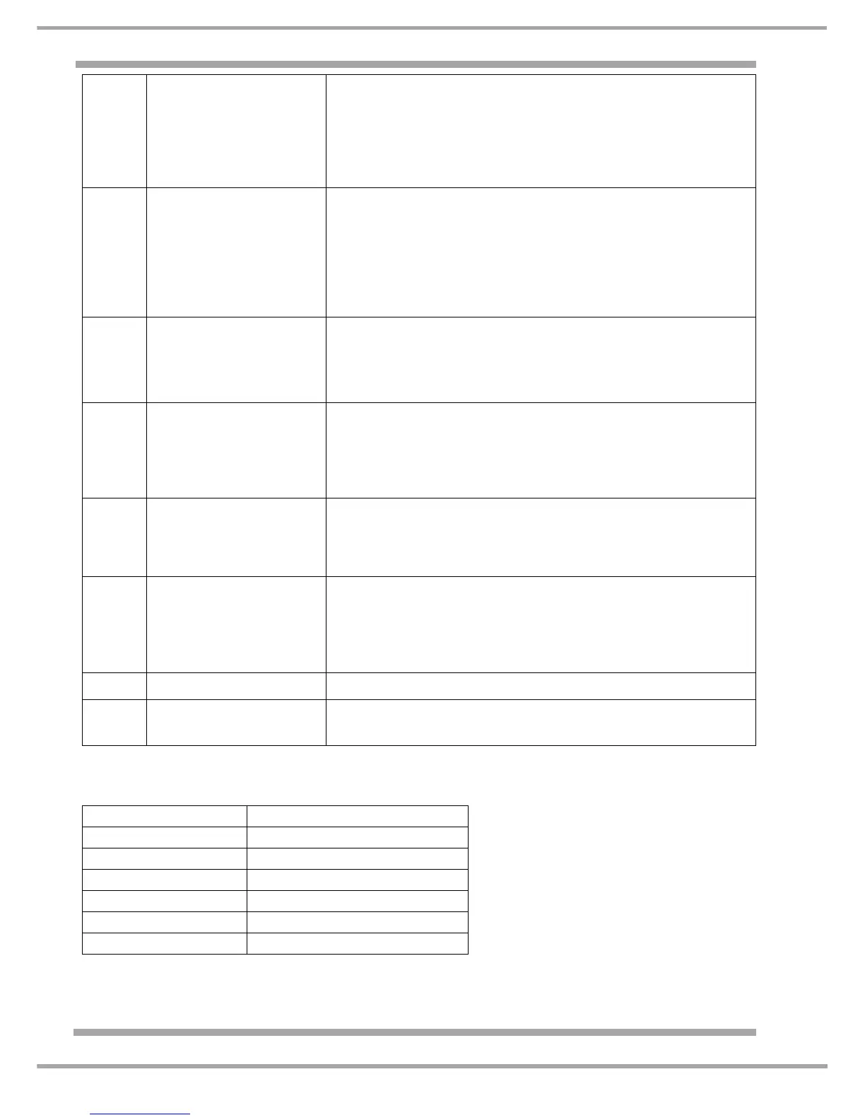
Thermistor Resistance Readings:
F10 Open circuit in the heater
Common wiring.
• Check the wiring between the cycling stat and the module;
•
Check wiring between module connector J4 and the heater;
•
Test heater elements.
Note:- Frequent cycling stat operation can cause F10, check
filter and condenser for blockages. The module checks and
waits 3 times before displaying F10.
F11 Open circuit pump circuit.
• Test continuity of pump;
•
Check connector J5;
•
Check wiring between pump and module J5.
Note:- F11 is usually caused by a fault in the pump circuit not
the module. Auto cycle being used fault displays within 1
minute Time and Wool cycles being used fault displays
at the end of the cycle.
F12 No communication
between display module
and control module.
• Check connector J9 on module;
•
Check wiring between module connector J9 and display;
•
Check display connector;
•
Replace module, display or wiring as required.
F13 Rear thermistor open or
short circuit.
• Check security of module connector J4;
•
Test from J4 connector pins 1 and 2 (approximately 500
Kohms);
•
If open circuit, test thermistor and wiring between thermistor
and J4 to locate fault.
F14 Upper element failure
• Check security of module connector J4;
•
Test between pins 4 and 5 on J4 (approximately 48 ohms);
•
If open circuit, test upper element and the wiring between J4
and the heater.
F15 Upper element is on when
it should be off.
• Check security of module connector J4;
•
Check connector for signs of shorting due to moisture;
•
Check heater elements and wiring;
•
Replace module (F15 would normally be caused by a faulty
module).
F16 Not used.
F17 Master Relay contacts
welded closed.
• Reverse polarity
• Replace module
Temperature
Resistance ( +/- 5% )
20°C
614 K Ohms
25°C
470 K Ohms
50°C
134 K Ohms
75°C
43.8 K Ohms
100°C
16.1 K Ohms
130°C
5.6 K Ohms