Application Note 14 2011-07-06
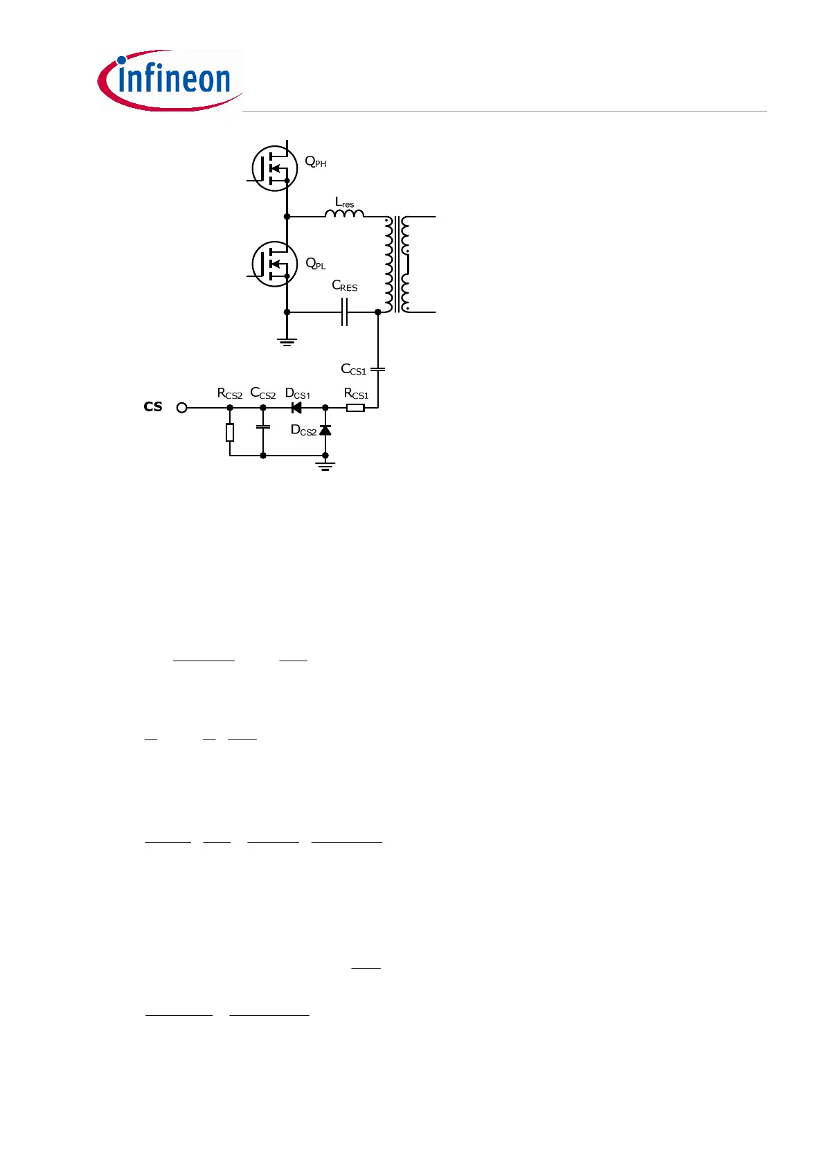
Figure 5 Current sense circuit
Assuming capacitive current divider is adopted as current sense circuit. So
1cs
C is chosen to be far less
than
r
C ,e. g, around 100/
r
C , say 470pF.
1cs
R is normally of a few hundred Ω for filtering purpose, say
200Ω.
We can obtain the following equation considering
1cs
C and
r
C as current divider:
r
cs
ocp
rcs
cs
ocpC
C
C
I
CC
C
II
cs
1
1
1
1
≈
+
= [21]
One major design criterion for the current sense is to ensure Over-Current Protection (OCP). Accordingly,
we can also obtain:
2
8.0
*
22
21
cs
RC
R
II
cscs
==
[22]
where 0.8V is the OCP first level.
Then we get:
Ω===
−
−
70
10*470
10*66
*
47.2*2
8.0
*
*2
8.0
12
9
1
2
ππ
cs
r
ocp
cs
C
C
I
R
[23]
Rcs2 is chosen as 68Ω.
2cs
C is selected so that the current loop speed is fast enough and the ripple on CS pin is around 20% of
the average value.
22
*
cscs
CR is around
min
1
f
.
nF
fR
C
cs
cs
490
10*30*68
1
*
1
3
min2
2
==≈
 Loading...
