Application Note 21 2011-07-06
2.4.3 Advanced Turn off delay
delayoff
T
_
- Delay pin
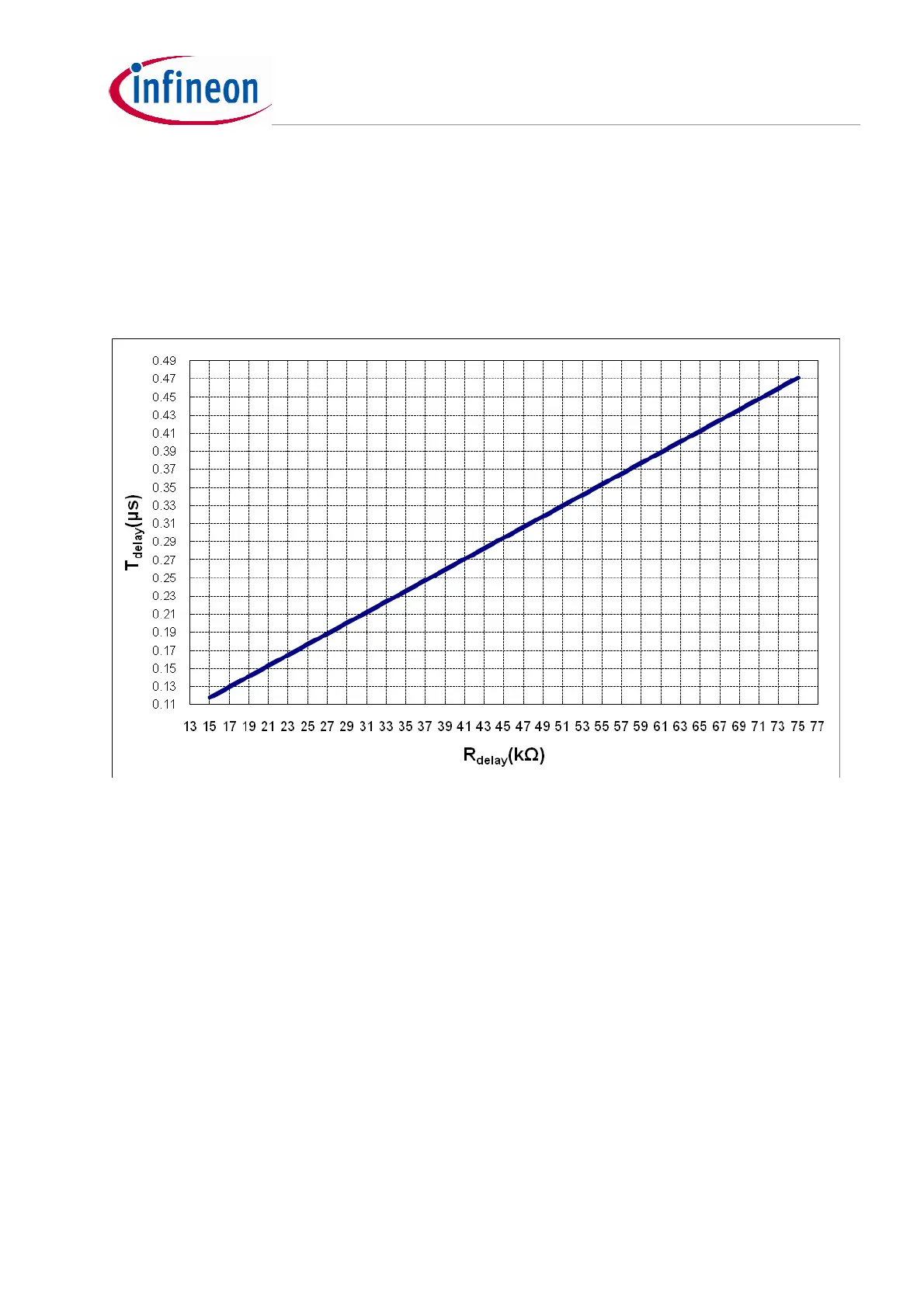
Advanced turn-off delay time of the SR MOSFET
delayoff
T
_
, normally is determined by the propagate
delay and transition time in the actual converter system. The value of
delayoff
T
_
can be set by the Delay
pin. For example, if the delay time required is 220ns, a
kR
delay
33 need to connect at Delay pin
according to the curve below.
Figure 11 Turn-off delay time versus Rdelay
2.4.4 A review of the control scheme
After all the SR related parameters have been set, such as maximum on-time
max_on
T , turn-on
delay
delayon
T
_
, advanced turn-off delay
delayoff
T
_
, simplified typical waveforms can be drawn in Figure 12
for the two conditions when
sw
f >
r
f and
sw
f <
r
f .
From the waveforms on the left, the switch-on of the SR MOSFET is
delayon
T
_
after the switch-on of the
primary side switch; while switch-off of the SR MOSFET is in advance with
delayoff
T
_
to the switch-off of
primary side switch. Under this operation condition, the SR MOSFET’s on-time changes with the primary
side MOSFET gate switching.
From the waveforms on the right, the SR MOSFET on-time is almost constant and equal to
max_on
T ,
which is independent of the primary side MOSFET turn-off.
In actual operation, the
sw
f doesn’t have to be monitored. SR MOSFET will be turned off by whichever
signal comes first – the turning-off of the primary gate, or the falling edge of
max_on
T .
 Loading...
