EasyManua.ls Logo

Infineon XMC4700 - User Manual

Infineon XMC4700
30 pages
Print Icon
To Next Page IconTo Next Page
Loading...
User manual
Please read the sections “Important notice” and “Warnings” at the end of this document
Revision 1.40
www.infineon.com
2023-02-14
User Manual
24 GHz radar tools and development
environment
XENSIV 24 GHz radar demo boards
About this document
Scope and purpose
This user manual describes the software and firmware environment required to use the radar applications
offered with Infineon’s industrial XENSIV™ 24 GHz radar demo boards: DEMO SENSE2GOL/MAKE, DEMO
DISTANCE2GO, DEMO POSITION2GO, DEMO SENSE2GOL PULSE and DEMO DISTANCE2GOL.
It provides guidelines for novice users on how to build and run smart radar solutions, from basic movement
detection to advanced motion detection and sensing, made easy with Infineon’s 24 GHz radar chipsets, and
using the Infineon firmware and software tools.
Intended audience
The intended audience for this document are design engineers, technicians, and developers of electronic
systems, working with Infineon’s XENSIV™ 24 GHz radar sensors.
Related documents
Additional information can be found in the documentation provided with the Radar Sense2GoL Pulse or Radar
Distance2GoL tools in the Infineon Developer Center (IDC), or from www.infineon.com/24GHz.
Note: Following the launch of our next generation of XENSIV Radar 24GHz DEMO boards with
SENSE2GOL PULSE and DISTANCE2GOL, please be informed that these XENSIV Radar 24GHz
demo boards are therefore discontinued: SENSE2GO, SENSE2GOL, DISTANCE2GO and
POSITION2GO.

Other manuals for Infineon XMC4700

Question and Answer IconNeed help?

Do you have a question about the Infineon XMC4700 and is the answer not in the manual?

Overview

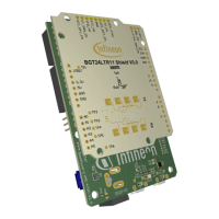
The Infineon XENSIV™ 24 GHz radar demo boards are comprehensive demonstration platforms and starter kits designed for developing and evaluating radar systems. These boards leverage Infineon's silicon-germanium (SiGe) based 24 GHz transceiver chipsets (BGT24) and 32-bit ARM® Cortex™-M based XMC™ microcontrollers, offering a robust foundation for various radar applications.

Function Description

The demo boards are engineered to facilitate the development of user applications capable of detecting motion, speed, direction of movement, distance, and position of multiple targets. They come pre-loaded with demonstration firmware and are supported by a highly interactive Graphical User Interface (GUI).

Several specific demo board variants are available, each tailored for different functionalities:

  • DEMO SENSE2GOL (S2GL): Based on the BGT24LTR11 and XMC1302, this board focuses on Doppler radar applications, enabling the detection of motion, speed, and direction of movement.
  • DEMO DISTANCE2GO (D2G): Utilizing the BGT24MTR11 and XMC4200, this board supports Frequency Modulated Continuous Wave (FMCW) and Doppler radar, allowing for the detection of distance, speed, and direction of movement.
  • DEMO POSITION2GO (P2G): Built with the BGT24MTR12 and XMC4700, this board employs fast-chirp FMCW for advanced tracking capabilities, including angle, distance, speed, and direction of movement detection.
  • DEMO SENSE2GOL PULSE (S2GLP): This variant combines an XMC4700 Radar Baseboard with a BGT24LTR11 Shield, offering Arduino compatibility. It specializes in Doppler radar for motion, speed, and direction of movement detection with a focus on extremely low power consumption.
  • DEMO DISTANCE2GOL (D2GL): Similar to the S2GLP, this board uses an XMC4700 Radar Baseboard and BGT24LTR11 Shield with Arduino compatibility. It supports Software-Controlled FMCW for detecting motion, speed, direction of movement of multiple targets, and the distance of the closest human or moving target, also with extremely low power consumption.

The core functionality revolves around providing a complete evaluation platform, including the necessary firmware and software tools to build and run smart radar solutions. This ranges from basic movement detection to more advanced sensing applications.

Usage Features

The demo boards are designed for ease of use, even for novice users, with a structured approach to setting up and running radar applications:

  • Software Setup: Users begin by downloading and installing the Infineon Developer Center (IDC) Launcher, which provides access to the 24 GHz radar software package and documentation. Through the IDC Launcher, users can install specific 24 GHz radar tools like Radar Sense2GoL, Radar Distance2Go, Radar Position2Go, Radar Sense2GoL Pulse, or Radar Distance2GoL.
  • Firmware Reprogramming: The XMC™ Flasher tool is provided for on-chip Flash programming, allowing users to reprogram the radar application using binary images (*.hex files). The Radar GUI also offers firmware flashing capabilities. Users connect the radar board to a PC via a USB "type A to micro-B" cable, start the XMC™ Flasher tool from the IDC launcher, connect to the device, select the appropriate binary file, and initiate the programming process. Successful programming is indicated by a "Programming is successful!" message.
  • Development Environment (DAVE™ IDE): For custom application development, Infineon provides DAVE™ (Digital Application Virtual Engineer), a free Eclipse-based Integrated Development Environment. DAVE™ supports C/C++ language software development and code generation, utilizing DAVE™ APPs to configure MCU peripherals, which simplifies development and porting of firmware across XMC™-series MCUs. Users can import existing DAVE™ projects, build them, and then flash and debug the customized firmware onto the radar demo board.
  • Graphical User Interface (Radar GUI): The Radar GUI is a Java-based, highly interactive tool for Windows. It visualizes real-time raw IF quadrature output signals, FFT spectrum, and displays target distance and velocity information. The GUI allows for recording data in various formats (raw data, time domain data, frequency domain data, and target data) for advanced signal processing. It also checks for firmware compatibility and prompts for updates if a newer version is available.
  • Micrium µC/Probe™ XMC™ GUI: This free data monitoring and visualization tool allows users to modify and track real-time data on the XMC™ target microcontroller non-intrusively. It enables the design of graphical dashboards with widgets and includes an eight-channel digital oscilloscope for real-time data visualization. This tool is specifically supported for DEMO SENSE2GOL/MAKE boards.
  • Raw Data Extraction: The boards support various interfaces for fetching raw data:
    • MATLAB Radar System Interface: Provides APIs and functions for accessing serial communication ports and communicating with radar-defined endpoints to extract raw IF data for signal processing in MATLAB. A coding example (extract_raw_data.m) is provided to guide users.
    • C Radar System Interface: Offers APIs for C-language applications to access serial communication ports and communicate with radar-defined endpoints. It supports Windows, Mac OS, and Linux platforms. A coding example (extract_raw_data.c) is available for users to integrate into their C projects.
    • UART Radar System Interface: Defines APIs for accessing serial communication ports and fetching sampled ADC data streamed via UART. This interface supports dumping ADC raw data (I and Q samples), Doppler measurements, and FFT spectrum. PuTTY, a free SSH, Telnet, and rlogin client, can be configured to fetch raw data streamed by UART.

Maintenance Features

The device manual outlines several aspects related to maintaining the functionality and ensuring optimal performance of the radar demo boards:

  • Firmware Updates: The IDC Launcher and Radar GUI actively check for newer firmware versions. Users are prompted to update the Radar GUI tool and the device firmware when updates are available, ensuring they are running the latest software for improved performance and features.
  • Driver Installation: Users are advised to ensure that SEGGER J-Link drivers are installed before using the XMC™ Flasher tool. This is crucial for proper debugger functionality and successful firmware programming.
  • Workspace Management: When using the DAVE™ IDE, it is recommended to keep the active workspace folder path short to avoid build errors caused by Windows path length limitations.
  • Project Rebuilding: Any changes made to the 
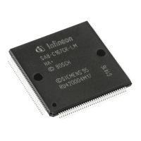
config.h file parameters for firmware customization require the project to be re-built and Flashed again. This ensures that the updated configurations are applied to the device.
  • Documentation Access: Comprehensive documentation, including application notes and hardware-related files (schematics, Altium files), is provided within the installed software package, allowing users to troubleshoot and understand the system in depth. The integrated Radar GUI help also offers a complete overview of its features.
  • Communication Protocol: The radar host communication protocol is a generic byte-stream protocol designed for robust message exchange between the host PC and the microcontroller. This protocol defines payload and status messages, ensuring reliable data transfer and device control. Endpoints are used to define functional groups and manage different message types, with version numbers to handle modifications.
  • Error Handling: The DAVE™ IDE includes features for debugging projects, allowing users to identify and resolve issues in their custom firmware. The XMC™ Flasher also indicates successful flashing or error messages, guiding users in case of programming failures.

Infineon XMC4700 Specifications

General IconGeneral
CoreARM Cortex-M4
Maximum Clock Frequency144 MHz
Flash Memory2 MB
RAM352 KB
Operating Voltage3.3 V
GPIO Pins144
ADC12-bit
DAC12-bit
Communication InterfacesEthernet, CAN, USB, UART, SPI, I2C
Operating Temperature-40 °C to 125 °C
PackageLQFP-144
PWMSupported via CCU4, CCU8
TimersMultiple, including CCU4, CCU8, POSIF, GPT12

Related product manuals