1
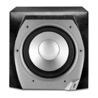
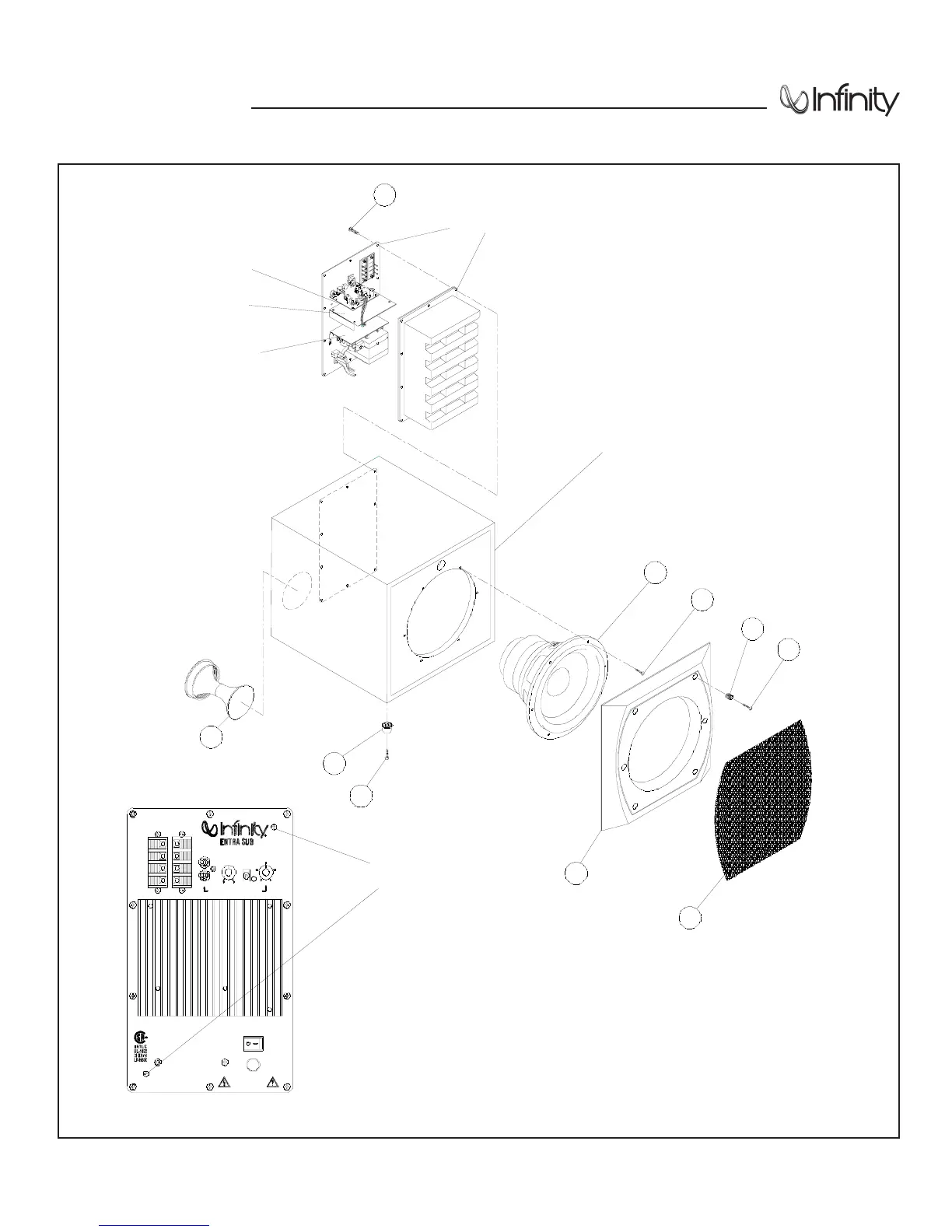
AMPLIFIER
(NOT FOR SALE)
PRE AMP
PCB ASSEMBLY
MAIN AMP
ASSEMBLY
POWER SUPPLY
PCB ASSEMBLY
2
1
3
4
5
6
1
7
8
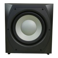
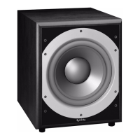
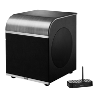
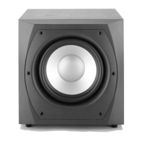
INFINITY
ENTRA SUBWOOFER
CABINET
(NOT FOR SALE)
00470
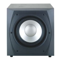
TO SERVICE THE ENTRA SUBWOOFER
1) Remove the grille.
2) Extract (6) rubber grille retainers as shown in the illustration above; this can be accomplished by
carefully pulling them out of the cavities with long-nosed pliers or similar tool.
3) Remove the (6) Phllips screws that are now exposed.
4) Remove the front baffle.
5) Remove the (6) screws that secure the driver.
6) To service the amplifier, remove the (10) Phillips screws at the rear of the enclosure, and pull
the amplifier out of the back. Remove the two Phillips screws as indicated in VIEW A to remove the rear cover.
VIEW A
REMOVE
THESE
SCREWS
INFINITY SYSTEMS INC. NORTHRIDGE, CA, USA
DIRECT
DIRECT INPUT BYPASSES FILTER
WARNING: TO REDUCE THE RISK OF FIRE OR ELECTRIC SHOCK, DO
NOT EXPOSE THIS APPLIANCE TO RAIN OR MOISTURE.
ATTENTION: P OUR ÉVITER TOUT RISQUE DE FEU OU CHOC
ÉLECTRIQUE , NE PAS EXPOSER CET APPAREIL À LA PLUIE OU À
L'HUMIDITÉ.
AM PLIFI ER MA DE IN CHINA
R
SERIAL NO.
SPEAKER LEVEL
INPUT
_
+
R
L
_
+
R
+
_
OUTPUT
L
_
+
LEVEL
LINE
INPUT
WARNING: SHOCK HAZARD- DO NOT OPEN
NO USER SERVICEABLE PARTS INSIDE
AVIS: RISQUE DE CHOC ÉLECTRIQUE-
NE PAS OUVR IR
1 20V ~ 60 Hz 3A
OFF
POW ER
ON
FRE Q UENCY
CROSSOVER
MAXMIN
180°
0°
60
50
LEVEL PHASE
80
150
120
R