EasyManua.ls Logo

Infinity PS-12 Service Manual

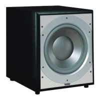
Infinity PS-12
33 pages
To Next Page IconTo Next Page
Page #1 background imageLoading...
Page #1 background image
PS-10
PS-12
PS Series Powered Subwoofers
SERVICE MANUAL
Infinity Systems Incorporated
250 Crossways Park Dr.
Woodbury, New York 11797 Rev1 10/2004

Other manuals for Infinity PS-12

Question and Answer IconNeed help?

Do you have a question about the Infinity PS-12 and is the answer not in the manual?

Infinity PS-12 Specifications

General IconGeneral
BrandInfinity
ModelPS-12
CategorySubwoofer
LanguageEnglish

Summary

Controls and Connections

Rear Panel

Identifies and describes the controls and connections located on the rear panel of the subwoofer.

System Connections

Connecting with LFE Output

Details how to connect the subwoofer using the LFE or subwoofer output from a Dolby Digital/DTS receiver.

Connecting with Speaker-Level Inputs

Explains how to connect the subwoofer using speaker-level inputs when an LFE output is not available.

Operation

Power On and Auto Standby

Instructions for powering on the subwoofer and details on its auto on/standby functionality.

Gain, Phase, and Crossover Adjustment

Guidance on setting gain, phase, and crossover frequency for optimal subwoofer performance.

Maintenance and Service

Cleaning and Connection Checks

Provides guidelines for cleaning the subwoofer and checking wiring connections for maintenance.

Troubleshooting and Seeking Service

Steps to take if a problem occurs and how to contact Infinity for service.

PS-10 Block Diagram

PS-12 Block Diagram

Test Setup and Procedures

System Aural Sweep Test

Details equipment and steps for performing an aural sweep test on the subwoofer.

General Unit Function Test

Step-by-step procedure for testing the general functionality of the subwoofer amplifier.

Sweep and Driver Function Tests

Instructions for testing cabinet, drivers, and woofer for noises using a sweep generator.

Technical Tips

Replacing Output MOSFETs

Provides specific instructions and part numbers for replacing output MOSFET transistors Q18 or Q22.

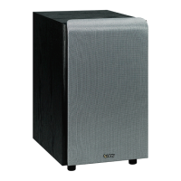
PS-10 Exploded View and Parts List

PS-12 Exploded View and Parts List

PS-10 Package Contents

PS-12 Package Contents

PS-10 Electrical Parts List (120V)

PS-12 Electrical Parts List (120V)

PS-10/PS-12 PCB Component Layout

PS-10/PS-12 PCB Trace Layout

Integrated Circuit and Transistor Diagrams

PS-10 Schematic Diagrams

PS-10 Schematic Diagrams (Continued)

PS-12 Schematic Diagrams

PS-12 Schematic Diagrams (Continued)

Related product manuals