15
3.5.0 X4 input - output command connector (Sub-D 25 points male)
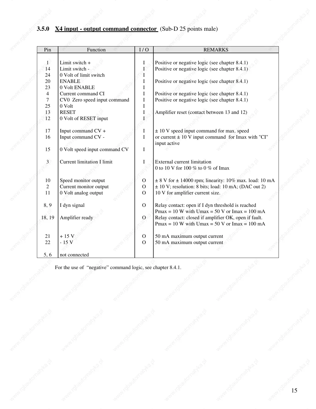
Pin Function I / O REMARKS
1 Limit switch + I Positive or negative logic (see chapter 8.4.1)
14 Limit switch - I Positive or negative logic (see chapter 8.4.1)
24 0 Volt of limit switch I
20 ENABLE I Positive or negative logic (see chapter 8.4.1)
23 0 Volt ENABLE I
4 Current command CI I Positive or negative logic (see chapter 8.4.1)
7 CV0 Zero speed input command I Positive or negative logic (see chapter 8.4.1)
25 0 Volt I
13 RESET I Amplifier reset (contact between 13 and 12)
12 0 Volt of RESET input I
17 Input command CV + I ± 10 V speed input command for max. speed
16 Input command CV - I or current ± 10 V input command for Imax with "CI"
input active
15 0 Volt speed input command CV I
3 Current limitation I limit I External current limitation
0 to 10 V for 100 % to 0 % of Imax
10 Speed monitor output O ± 8 V for ± 14000 rpm; linearity: 10% max. load: 10 mA
2 Current monitor output O ± 10 V; resolution: 8 bits; load: 10 mA; (DAC out 2)
11 0 Volt analog output O 10 V for amplifier current size.
8, 9 I dyn signal O Relay contact: open if I dyn threshold is reached
Pmax = 10 W with Umax = 50 V or Imax = 100 mA
18, 19 Amplifier ready O Relay contact: closed if amplifier OK, open if fault.
Pmax = 10 W with Umax = 50 V or Imax = 100 mA
21 + 15 V O 50 mA maximum output current
22 - 15 V O 50 mA maximum output current
5, 6 not connected
For the use of “negative” command logic, see chapter 8.4.1.
 Loading...