17
4.0.0 CONNECTIONS
4.1.0 Connection diagrams
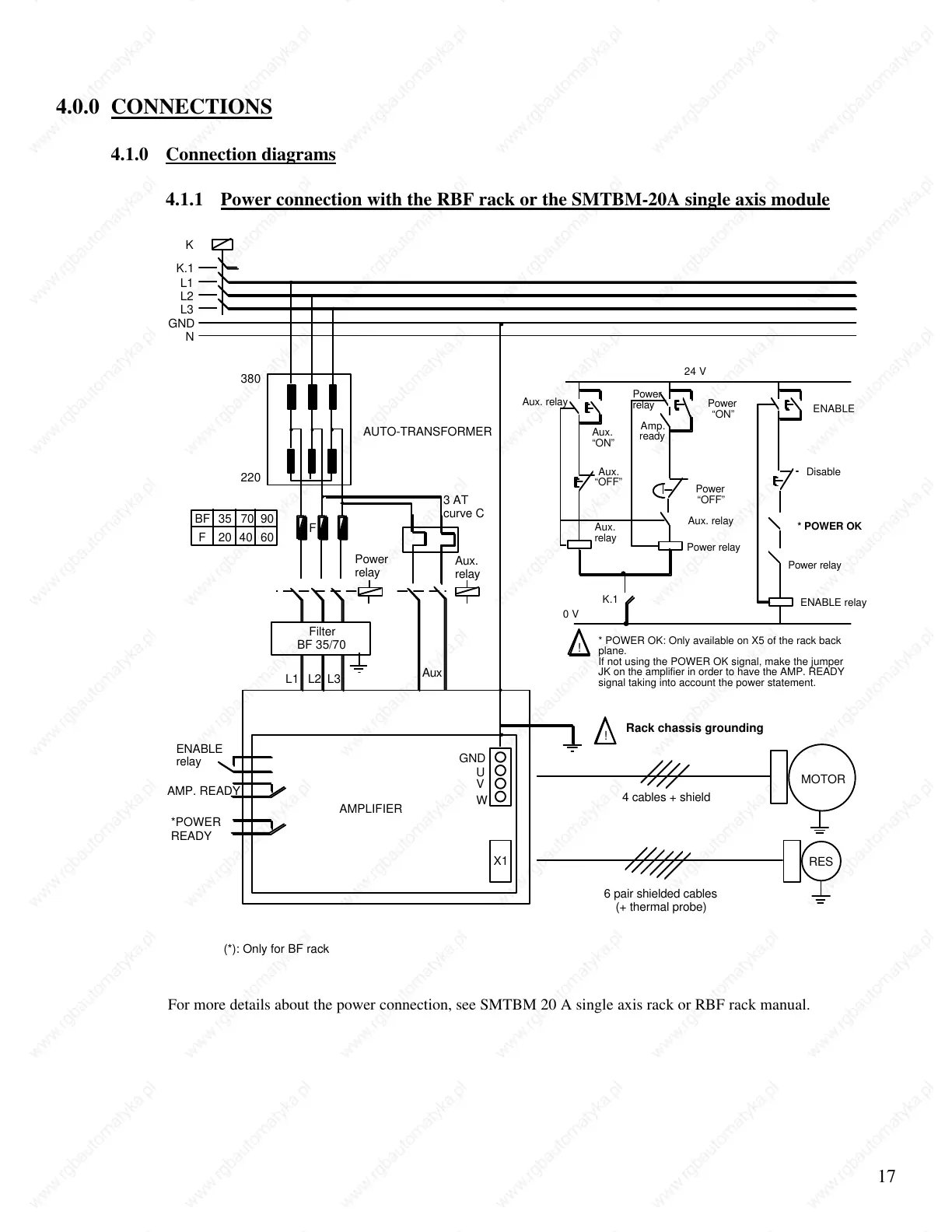
4.1.1 Power connection with the RBF rack or the SMTBM-20A single axis module
K
K.1
L1
L2
L3
N
380
220
F
Power
relay
Aux.
relay
U
V
W
GND
X1
AMPLIFIER
ENABLE
relay
AMP. READY
*POWER
READY
MOTOR
RES
4 cables + shield
6 pair shielded cables
(+ thermal probe)
!
Rack chassis grounding
(*): Only for BF rack
BF 35 70 90
F 20 40 60
AUTO-TRANSFORMER
3 AT
curve C
L1 L2 L3
Filter
BF 35/70
Aux
GND
!
* POWER OK: Only available on X5 of the rack back
plane.
If not using the POWER OK signal, make the jumper
JK on the amplifier in order to have the AMP. READY
signal taking into account the power statement.
Aux.
“ON”
Aux.
“OFF”
K.1
ENABLE
Power
“ON”
Power
“OFF”
Aux. relay
Power relay
Disable
* POWER OK
ENABLE relay
24 V
0 V
Amp.
ready
Aux. relay
Power
relay
Aux.
relay
Power relay
For more details about the power connection, see SMTBM 20 A single axis rack or RBF rack manual.
 Loading...