40
The maximum current duration before the release of the Idyn signal output (t1 - t0) and before the rated
current limitation (t2 - t0) is calculated the same way as for the Fusing mode.
8.4.0 Logic control adjustment
8.4.1 Positive or negative logic inputs
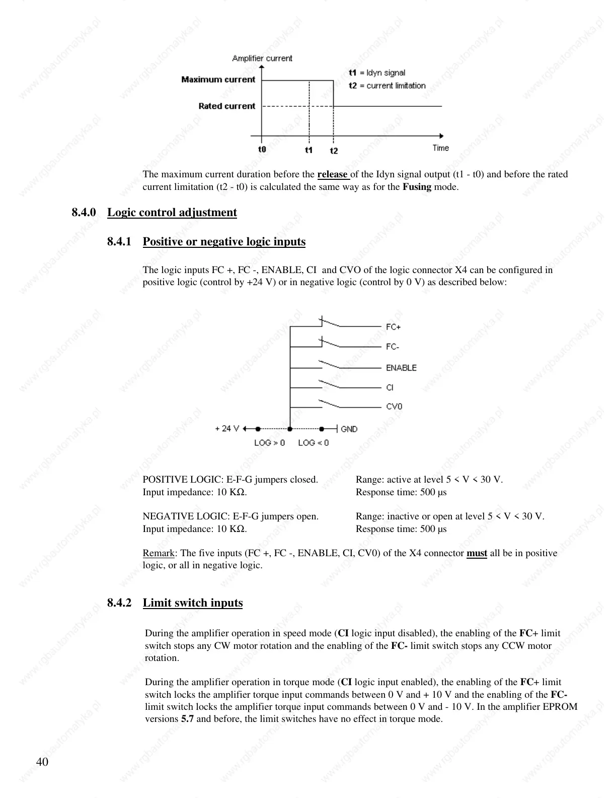
The logic inputs FC +, FC -, ENABLE, CI and CVO of the logic connector X4 can be configured in
positive logic (control by +24 V) or in negative logic (control by 0 V) as described below:
POSITIVE LOGIC: E-F-G jumpers closed. Range: active at level 5 < V < 30 V.
Input impedance: 10 KΩ. Response time: 500 µs
NEGATIVE LOGIC: E-F-G jumpers open. Range: inactive or open at level 5 < V < 30 V.
Input impedance: 10 KΩ. Response time: 500 µs
Remark: The five inputs (FC +, FC -, ENABLE, CI, CV0) of the X4 connector must all be in positive
logic, or all in negative logic.
8.4.2 Limit switch inputs
During the amplifier operation in speed mode (CI logic input disabled), the enabling of the FC+ limit
switch stops any CW motor rotation and the enabling of the FC- limit switch stops any CCW motor
rotation.
During the amplifier operation in torque mode (CI logic input enabled), the enabling of the FC+ limit
switch locks the amplifier torque input commands between 0 V and + 10 V and the enabling of the FC-
limit switch locks the amplifier torque input commands between 0 V and - 10 V. In the amplifier EPROM
versions 5.7 and before, the limit switches have no effect in torque mode.
 Loading...