39
8.3.3 I
2
t protection
Current limitation in Fusing mode
When the amplifier RMS current (I
2
t) reaches 85% of the Rated current, the Idyn signal output is activated
and the I
2
t error display flashes on the amplifier front panel. If the RMS current (I
2
t) has not dropped
below 85 % of the Rated current within 1 second, the I
2
t default is released and the amplifier is disabled
(otherwise, the Idyn signal and the flashing I
2
t error display are both eliminated).
When the amplifier RMS current (I
2
t) reaches the Rated current value, the I
2
t protection limits the
amplifier current to this value.
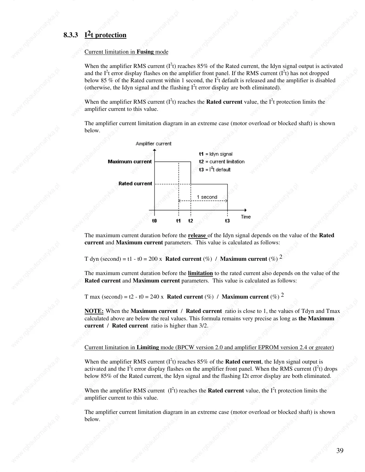
The amplifier current limitation diagram in an extreme case (motor overload or blocked shaft) is shown
below.
The maximum current duration before the release of the Idyn signal depends on the value of the Rated
current and Maximum current parameters. This value is calculated as follows:
T dyn (second) = t1 - t0 = 200 x Rated current (%) / Maximum current (%)
2
The maximum current duration before the limitation to the rated current also depends on the value of the
Rated current and Maximum current parameters. This value is calculated as follows:
T max (second) = t2 - t0 = 240 x Rated current (%) / Maximum current (%)
2
NOTE: When the Maximum current / Rated current ratio is close to 1, the values of Tdyn and Tmax
calculated above are below the real values. This formula remains very precise as long as the Maximum
current / Rated current ratio is higher than 3/2.
Current limitation in Limiting mode (BPCW version 2.0 and amplifier EPROM version 2.4 or greater)
When the amplifier RMS current (I
2
t) reaches 85% of the Rated current, the Idyn signal output is
activated and the I
2
t error display flashes on the amplifier front panel. When the RMS current (I
2
t) drops
below 85% of the Rated current, the Idyn signal and the flashing I2t error display are both eliminated.
When the amplifier RMS current (I
2
t) reaches the Rated current value, the I
2
t protection limits the
amplifier current to this value.
The amplifier current limitation diagram in an extreme case (motor overload or blocked shaft) is shown
below.
 Loading...