21
SPEED: This function allows the control of the motor speed by means of the PC during the commissioning and
adjustment phases.
• The digital speed input command value (in rpm) is entered into the Reference block.
• The three buttons in the Speed block give a positive (>>), negative (<<) or zero (0) speed input command.
ERROR MESSAGE: This function displays the error information. The stored errors can be canceled by the Reset
function.
5.1.2 Adjustment panel
The main adjustable parameters as well as the automatic commissioning aid functions are accessible in the
adjustment panel. The whole system is represented as a block diagram for a better display of the parameters.
ANALOG INPUT: This module concerns the adjustable parameters for motor speed input command.
• The Max speed parameter defines the maximum motor rotation speed for an input command voltage of 10 V
on the CV input of X4. The adjustment range is between 100 and 14000 rpm. This parameter is automatically
calculated with regard to the rated speed value (Rated speed) entered by the operator.
• The Rated speed (rpm) parameter defines the motor rated speed for an input command of 8, 9V or 10V on the
CV input of X4. The adjustment range is between 80 and 11200 rpm for an 8 V input command and between
90 and 12600 rpm for a 9 V input command. If this parameter is modified after the encoder programming
output, check that the new max. speed value is compatible with the Encoder resolution parameter.
• The Accel time parameter defines the motor acceleration or deceleration time between 0 and the max speed
value defined above. The adjustment range is between 0 and 30 s.
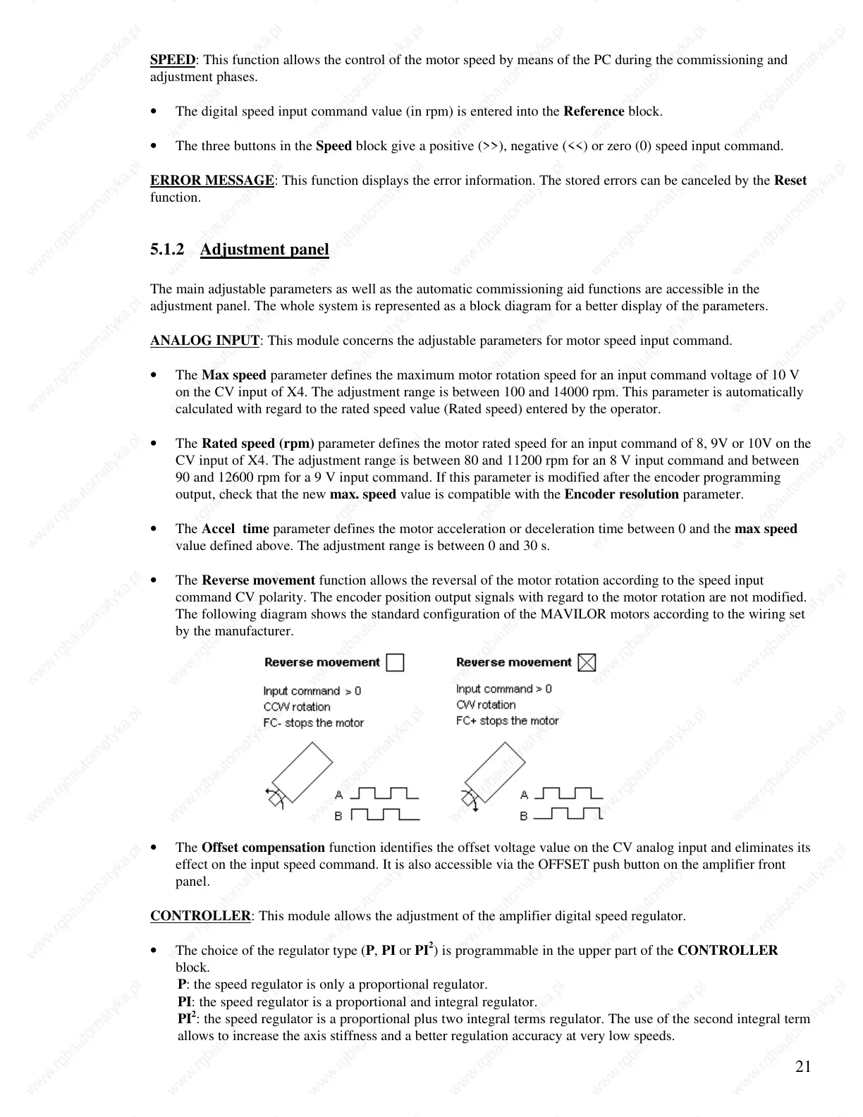
• The Reverse movement function allows the reversal of the motor rotation according to the speed input
command CV polarity. The encoder position output signals with regard to the motor rotation are not modified.
The following diagram shows the standard configuration of the MAVILOR motors according to the wiring set
by the manufacturer.
• The Offset compensation function identifies the offset voltage value on the CV analog input and eliminates its
effect on the input speed command. It is also accessible via the OFFSET push button on the amplifier front
panel.
CONTROLLER: This module allows the adjustment of the amplifier digital speed regulator.
• The choice of the regulator type (P, PI or PI
2
) is programmable in the upper part of the CONTROLLER
block.
P: the speed regulator is only a proportional regulator.
PI: the speed regulator is a proportional and integral regulator.
PI
2
: the speed regulator is a proportional plus two integral terms regulator. The use of the second integral term
allows to increase the axis stiffness and a better regulation accuracy at very low speeds.
 Loading...