7
trapuls – EtherCAT® Fieldbus Interface
Chapter 2 – Basic information about EtherCAT®
2.3 - ETHERCAT® FIELDBUS TOPOLOGY
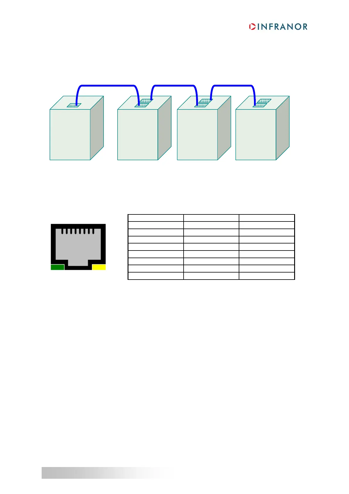
In motion control applications, EtherCAT® slaves are connected together in one line. The physical layer
technology employed by the EtherCAT® fieldbus is the 100BASE-TX. The EtherCAT® master is connected at
one end of the line.
RJ-45 sockets on EtherCAT® slaves are labelled “IN” and “OUT”.
The EtherCAT® master should be connected to the first EtherCAT® slave using the “IN” RJ-45 socket of the
EtherCAT® slave.
The cables used for an EtherCAT® network need to be of category 5e quality. Maximum cable length should be
100 m. The following table indicates the pin function and the wire colors (see T 568-B standard for more
information).
Pin T568B Color Function
1 white/orange stripe TxData +
2 orange solid TxData -
3 white/green stripe RecvData +
4 blue solid Not used
5 white/blue stripe Not used
6 green solid RecvData -
7 white/brown stripe Not used
8 brown solid Not used
IN
T
EtherCAT®
Slave
1
IN
T
EtherCAT®
Slave
2
IN
T
EtherCAT®
Slave
n
EtherCAT®
Master
1
8