Do you have a question about the Ingersoll-Rand SE and is the answer not in the manual?
Introduces the SE controller, its purpose, and basic operation for IR compressors.
Explains the SE controller's printed circuit board, CPU, and EPROM.
Details the functions of buttons like Start, Stop, Load, Unload, and Display Select.
Describes how the SE controller displays current operating parameters like pressure and temperature.
Explains normal display messages for running and non-running compressor states.
Explains how to access hidden functions like Last Alarm Recall for advanced diagnostics.
Lists available factory set points for language, pressure units, and starter options.
Details the ten main set points adjustable by the operator for compressor control.
Describes the warning for excessive air end discharge temperature.
Explains the warning for separator element pressure differential.
Details the warning message indicating scheduled maintenance is due.
Explains the alarm condition for low wet-side sump pressure.
Describes the alarm for exceeding package discharge pressure limits.
Details the alarm for excessive air/oil temperature leaving the airend.
Covers faults related to starters, main motor overload, and fan motor overload.
Details sensor failures, remote stop issues, and lack of control power.
Explains settings like AUTO S/S, SEQUENCER, REMOTE S/S, and LOW AMBIENT.
Describes the function and reset procedure for the Emergency Stop button.
Explains the automatic shutdown feature for energy saving and reduced running time.
Details the steps for calibrating the 3APT pressure transducer for accurate readings.
Describes the 2 ATT thermistor sensor and its role in monitoring temperature.
Provides a chart of input/output signals, terminals, and voltage states for wiring.
Explains setting and toggling between two different pressure set points for flexibility.
Describes the front panel controls and indicators for UP series compressors.
Provides questions to test understanding of SE Controller functions, warnings, and alarms.
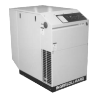
The Ingersoll Rand SE Controller is a microprocessor-based control system designed for 50-100hp (37-75kW) IR Contact Cooled Rotary Compressors. It utilizes a finger-touch membrane for operation and setting control parameters, with information displayed on a Liquid Crystal Display (LCD) showing temperature and pressure readings. The Intellisys system monitors the compressor and automatically issues warnings or alarms to shut down the compressor if pre-programmed limits are exceeded. A network of pressure and temperature sensors, relays, and switches supports the controller's decision-making process.
The SE Controller's primary function is to manage and monitor the compressor's operating functions. It uses software programmed into an EPROM (Erasable Programmable, Read Only Memory) chip to execute all necessary operations. The controller continuously monitors various parameters and provides real-time status updates.
Key Functions:
| Brand | Ingersoll-Rand |
|---|---|
| Model | SE |
| Category | Controller |
| Language | English |