Do you have a question about the Ingersoll-Rand ST400 and is the answer not in the manual?
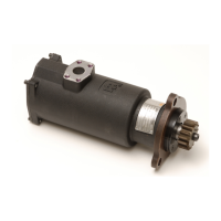
Overview of the compressed air powered Turbine Engine Starters.
Essential safety guidelines for operating the starter.
Safety precautions for installing and putting the starter into service.
Safety precautions for operating the starter.
Explanation of safety symbols used in the manual.
Guidelines for orienting the air starter for specific installation requirements.
Information on how to order various system components for the starter.
Instructions for mounting the valve to the air receiver.
Steps for determining hose length and mounting the starter to the engine.
Procedures for pressurizing the system and checking for air leaks.
General guidelines for starter disassembly and handling.
Step-by-step instructions for disassembling the starter.
Instructions for general assembly and starter reassembly.
Steps for testing and inspecting the starter after assembly.
Steps for disassembling the manual valve.
Steps for assembling the manual valve.
Diagnostic flowchart for ST400 starter system issues.
This document provides installation and maintenance information for Turbine Powered Starters, Model ST400, manufactured by Ingersoll Rand. These starters are designed to be integrated into systems primarily for initiating the operation of reciprocating internal combustion engines.
Users are strongly advised to read and understand this manual before operating the product. It is crucial to make this safety information available to anyone who will operate the starter. Failure to adhere to the warnings provided could result in injury.
Installation, operation, inspection, and maintenance must always comply with all applicable standards and regulations (local, state, country, federal, etc.). ST400 Starters are designed for operation exclusively on compressed air; they are not sealed or intended for use with compressed gas. All air supply lines and fittings must be of the proper size and securely tightened. An accessible emergency shut-off valve should be installed in the air supply line, and its location should be known to all operators. The starter requires clean, dry air at pressures not exceeding the maximum inlet pressure rating specified on the product nameplate. Operating at higher pressures can lead to hazardous situations, including excessive speed, rupture, or incorrect output torque.
Before installing, removing, or adjusting any accessory, or performing any maintenance, the air supply must be turned off and the air supply hose disconnected. The starter should only be operated when properly installed on the engine. Damaged, frayed, or deteriorated air hoses and fittings must not be used. For cleaning parts, only proper cleaning solvents that meet current safety and health standards should be used, and cleaning should be done in a well-ventilated area. All labels must remain intact, and any damaged labels should be replaced. The starter is not insulated from electric shock. Given that starters weigh over 25 pounds (11.3 kgm), caution is advised during handling.
The manual includes symbols to identify necessary safety precautions:
The use of non-genuine Ingersoll Rand replacement parts may lead to safety hazards, decreased motor performance, increased maintenance, and could invalidate all warranties. Ingersoll Rand is not responsible for customer modifications to motors for applications not consulted with them. Repairs should only be performed by authorized trained personnel. Users should consult their nearest Ingersoll Rand Authorized Service Center for assistance. At the end of the starter's life, it is recommended that it be disassembled, degreased, and parts separated by material for recycling. Manuals can be downloaded from www.ingersollrandproducts.com.
The manual provides a detailed guide on how to order a starter, including a breakdown of the model number (ST400 IC 03 R 31-030) which specifies arc percentage, inlet type, cradle/SAE flange mount, rotation, and pinion code. A table lists correct pinion data based on teeth, D.P., MOD., P.A., rotation, and pinion part number. For different models or special applications, users are advised to contact an Ingersoll Rand distributor or Ingersoll Rand Engine Starting Systems.
Instructions are also provided for orienting the air starter, which may be necessary if the starter was not ordered with the correct orientation for specific mounting or installation requirements. This involves loosening flange screws, rotating the flange to the desired orientation using marks on the housing (each mark representing 30° of arc, with a "0" mark aligning with the starter inlet), and then tightening the flange screws to a specified torque. To purchase a pre-oriented starter, users need to provide an orientation code, which is an angular measurement derived from a clockwise measurement of the angle from the "0" mark (inlet port) to the reference hole of the Mounting Flange.
The manual also illustrates how to order system components, including electronic and manual valves, split flanges, and tank flanges, along with their respective part numbers and dimensions.
Before connecting the starter to an air receiver tank already in service, the air pressure in the tank must be bled off.
The ST400-A339 or ST400-B339 Electronic Valve or ST400-A339M Manual Valve should be mounted to the air receiver as shown in the installation diagrams. The air flow arrow must point towards the starter. The supplied flange fitting should be used, and the four flange bolts tightened to the specified torque. For electrical installations, the ST400-A618 Electrical Switch should be installed on the dash panel, with wire connections made as shown in the relevant diagram. For air installations, the SMB-618 Starter Control Valve should be installed on the dash panel, with air lines connected as shown.
To determine the required length of hose, a piece of hose or flexible tubing of the same diameter should be run from the valve on the air receiver to the starter mounting location on the engine. Once the hose length is determined, O-ring sealed flange fittings should be attached. The hose should then be attached to the outlet side of the valve using the ST400-16 4-bolt split-flange, with bolts tightened to the specified torque. It should be determined if it is convenient to attach the hose to the starter before mounting it on the engine. If possible, the teeth of the ring gear should be liberally greased with a good, sticky gear grease or motorcycle chain lubricant to promote the life of the starter pinion and engine ring gear. Finally, the starter should be mounted in position and bolted to the engine.
After pressurizing the complete starting system, a soapy solution should be used to check for leaks at the valve/tank connection, fill-line to check valve on ST400 valve, and air supply line to 2-way check valve.
The manual includes detailed installation diagrams for stationary industrial setups, electro-mechanical systems, and manual systems, showing the placement of components such as strainers, pressure gauges, relay valves, inlet flange kits, and various hoses and connectors.
Detailed dimensions for the ST400 starter are provided, including measurements for the flange, housing, and other components, along with notes on weight and flange rotation.
Dimensions for the ST400-C339 Electronic Valve and ST400-A339M Manual Valve are also provided, showing various ports, threads, and flange styles.
Always wear eye protection when operating or performing any maintenance. The air supply must be turned off and disconnected before any work. Disassembly should only proceed as far as necessary to replace worn parts. When gripping parts in a vise, leather-covered or copper-covered vise jaws must be used to prevent distortion, especially for threaded members. Parts that are press-fit should only be removed if necessary for replacement or repairs. A complete set of seals and O-rings should be on hand before any overhaul, and old seals or gaskets should never be reused. Adjacent parts should be marked during disassembly to ensure correct reassembly. The Liner Assembly (9) should never be washed in a solvent.
Always press on the inner ring of a ball-type bearing when installing it on a shaft, and on the outer ring when pressing it into a bearing recess. When gripping a starter or part in a vise, use leather-covered or copper-covered vise jaws, taking extra care with threaded parts or housings.
WARNING: When 90 psig air pressure is applied to the starter, the Drive Pinion will rotate at 2,800 rpm and the Drive Shaft and Drive Pinion will move forward 1.25". Keep face and hands away from the rotating Drive Pinion. CAUTION: Do not run the starter at free speed.
The Mounting Flange must be oriented per the customer's order or engineering drawing. If orientation is not specified, standard orientation will be supplied. Users should check the orientation print on page 5.
Turn the Drive Pinion by hand in the direction of rotation. The clutch should ratchet smoothly.
Turn the Drive Pinion by hand in the direction opposite of rotation. The clutch should not ratchet.
An exploded view and a detailed part list are provided for the manual valve assembly, identifying components such as the valve housing, O-rings, housing cover, valve kit (including O-ring, plunger, pin assembly, grommet seal, and diaphragm assembly), cap, spring, check valve, plugs, cover screws, flange assembly, and male connector.
Always wear eye protection when operating or performing any maintenance on this valve. Turn off the air and electrical supply and disconnect them before any work. Disassembly should only proceed as far as necessary to replace worn parts. When gripping parts in a vise, use leather-covered or copper-covered vise jaws to prevent distortion, especially for threaded members. Parts that are press-fit should only be removed if necessary for replacement or repairs. A complete set of seals and O-rings should be on hand before any overhaul, and old seals or gaskets should never be reused.
Whenever gripping a valve or part in a vise, use leather-covered or copper-covered vise jaws. Apply a film of O-ring lubricant to all O-rings before final assembly.
Using a solenoid tester, apply 9 VDC minimum to 24 VDC maximum to the Solenoid. The Solenoid should activate the Armature with a minimum 9-volt charge, and a "clicking" sound indicates proper functioning. This procedure applies to both the Exhaust Solenoid and the Pressure Solenoid.
The manual includes flowcharts for diagnosing common issues:
| Input Voltage | 24 VDC |
|---|---|
| Output Voltage | 24 VDC |
| Enclosure Rating | IP20 |
| Number of Inputs | 16 Digital Inputs |
| Number of Outputs | 16 Digital Outputs |
| Controller Type | PLC |
| Humidity Range | 5 to 95% RH, non-condensing |
| Communication Protocol | Modbus TCP/IP |