Placing System in Service
When connecting the starter to an air receiver tank that is already in service, bleed o the air pressure in the tank prior to installation.
Valve
Mount the ST400-A339 or ST400-B339 Electronic Valve or ST400-A339M Manual Valve to the air receiver as shown in the installation
diagrams.
Air ow arrow must point toward the starter.Using the supplied ange tting, tighten the four ange bolts to 28-35 ft-lbs (38-47 Nm) torque.
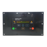
For electrical installations, install the ST400-A618 Electrical Switch on the dash panel. See Dwg. TPB973 for making wire connections. For air
installations, install the SMB-618 Starter Control Valve on the dash panel. Connect the air lines as shown in Dwg. TPB976.
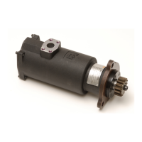
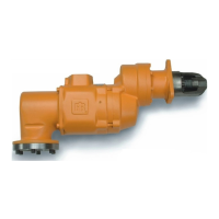
Mounting the Starter
To determine the exact length of #16 hose required, run a piece of hose or some other exible tubing of the same diameter from the valve
on the air receiver to the starter mounting location on the engine. After determining the hose length required, attach O-ring sealed ange
ttings as required.
Attach the hose to the outlet side of the valve with the ST400-16 4 bolt split-ange provided. Tighten bolts to 28-35 ft-lbs (38-47 Nm) torque.
At this point, determine if it is convenient to attach the hose to the starter before actually mounting it on the engine.
If possible, liberally grease the teeth of the ring gear with a good, sticky gear grease or motorcycle chain lubricant. This will help to promote
the life of the starter pinion and engine ring gear.
Mount the starter in position and bolt it to the engine.
System Actuation
Pressurize the complete starting system and using a soapy solution, check the following locations in the live air line for leaks:
Valve/tank connection
Fill-line to check valve on ST400 valve
Air supply line to 2-way check valve
1.
2.
3.
1.
2.
3.
4.
5.
•
•
•
ST400 Installation Diagram - Stationary Industrial
�Inlet Flange Kit
ST400-K17
�Relay Valve 1”
SRV100 Or ST400-A339M
High Pressure
Supply
ST900-267-16
Strainer
1” Hose
# 4 Hose 1/4”
# 4 Hose 1/4”
Air Pressure Gauge
�150BMP-1064L (Air Only)
NOTE :
Use sealant on All pipe Connections.
� SMB-441
� Ingersoll Rand Part Numbers
(Dwg.TPA1592)

 Loading...
