Orientation of the Air Starter
We recommend that starters be ordered to proper orientation for
your specic mounting or installation requirements. However, if the
starter must be reoriented for installation, proceed as follows
Loosen six ange screws.
Turn Flange to desired orientation. Note the orientaion marks on
the exterior ofthe Housing. Each mark measures 30° of arc. There
is a “0” mark which alligns with the starter inlet.
Tighten the six ange screws to 3-4 ft. lbs. (4-6 Nm) torque.
To purchase pre-oriented starter:
It is necessary to provide the orientation code which is the angle
of the Mounting Flange relative to the starter inlet port (“0” mark
on the Housing). Therefore, the orientation code will be an angular
measurement. To obtain the orientation code, proceed as follows:
1.
2.
3.
Orient the starter so that the inlet port is pointed straight up. The
“0” mark on the Housing near the Mounting Flange should be
visible and pointed straight up.
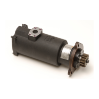
With the starter at this setting, position yourself so that the Drive
Pinion (2) is facing you.
Rotate the Mounting Flange clockwise until the desired
orientation is reached.
You will derive the orientation code from a clockwise
measurement of the angle from the “0” mark (inlet port) to the
reference hole of the Mounting Flange. The Housing has indicator
marks every 30° . Example: ST400C03R31-060.
1.
2.
3.
4.
0
180
SAE 03 Flange
SAE 01 Flange
210
90
60
30
240
120
Left Hand
Rotation
150
270
300
330
Ref. Hole
of Mounting Flange
Ref. Hole
of Mounting Flange
Right Hand
Rotation
(Dwg. TPD1670-1)
How to Order System Components
ST400-C339 Electronic Valve
ST400-A339M Manual Valve
45° Split Flange /37° Flare
ST400-23
90° Split Flange /37° Flare
ST400-162
Split Flange /37° Flare
ST400-25
 Loading...