4
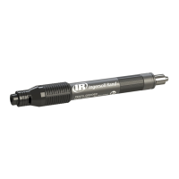
PLACING TOOL IN SERVICE
TRIMMER GUIDE
Trimmer Guide Dimensions
OFFSET
(Dwg. TPD1208)
PART NUMBER FOR ORDERING A B C D E
R120–128–2 (for 1/4” shank) 1–1/2 3/8 3/8 1/8 1/2–20NF
R120–128–7 (for 1/4” shank) 2–1/2 1/2 1/2 3/16 1/2–20NF
LG2–129–1 (for 3/8” shank) 2–1/2 1/2 5/8 1/8 5/8–18UNF
K Note: Offset = 1/2 (“B” dimension minus trimmer bit diameter.)
The following equipment is available at an extra price and must be ordered separately:
1. Router Attachment Assembly
for models using 1/4” diameter bits Part No. TD–RK4. . . . . . . . . . . . . . . . . . . . . . . . . . . . . . . . . . . . . . . . . . .
for models using 3/8” diameter bits Part No. TD–RK6. . . . . . . . . . . . . . . . . . . . . . . . . . . . . . . . . . . . . . . . . . .
2. Trimmer Guide (for Router Attachments)
for 1/4” shank Part No. R120–128–2. . . . . . . . . . . . . . . . . . . . . . . . . . . . . . . . . . . . . . . . . . . . . . . . . . . . . . . . . . . .
for 1/4” shank Part No. R120–128–7. . . . . . . . . . . . . . . . . . . . . . . . . . . . . . . . . . . . . . . . . . . . . . . . . . . . . . . . . . . .
for 3/8” shank Part No. LG2–129–1. . . . . . . . . . . . . . . . . . . . . . . . . . . . . . . . . . . . . . . . . . . . . . . . . . . . . . . . . . . .
All the models listed on Page 5 can be changed to front exhaust tools by reversing the Flow Ring and aligning the the indicator
marks with the letter “F” on the Housing. To order a front exhaust tool from the factory, substitute the letter “F” for the letter
“R” in the above models. Example: TD12RG4 Rear Exhaust Model becomes TD120FG4 Front Exhaust Model.
 Loading...