32 Installation instructions
Conventional fire detection control panel
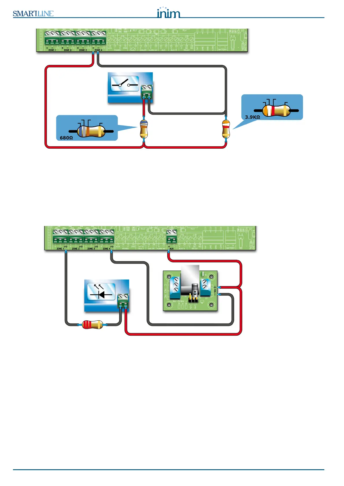
Figure 18 - Connecting generic contacts to the detection line
The wiring diagram above illustrates the connection of a generic device (call point, switch, generic device
output) to the detection line. If the line is wired in this way, it will signal a fault when a short-circuit or
cable interruption occurs, and will generate the pre-set line signals (alarm, sprinkler, change class, etc.)
when the contact closes.
6.5.2 Connecting I/O Lines
Each zone I/O line can be wired in one of the following ways:
Figure 19 - Wiring the I/O line as an output
The diagram above illustrates a line wired as an output. The terminal will operate in the same way as an
open-collector output, that is, it will be open during standby status and close to Ground (-) in the event of
activation.
ORANGE
WHITE RED
GOLD
BLUE
GRAY BROWN
GOLD
CONTACT
LED
SIGNALLING
REL1INT
1 relay board