16 Zone Expansion Board. Installation Guide.
Revision 2.0 March. 2005.
3
2
Expander Module 16 Zone Expansion Board Kit
- 16 Zone Expansion board sub-assy.
- 5 x 8 way plug-on screw terminals
- 1 x 20 way Ribbon cable. 400mm.
- 1 x 20 way Ribbon cable. Short.
- 4 x M3 screws.
- 4 x Metal M3 Mounting Clips for use in the Universal Enclosure range.
- 2 x 35mm Metal M3 PCB standoffs for mounting the board above the Universal
Expander board if necessary.
- 20 x 2k2 End-of-line resistors. (red-red-black-brown-brown)
- 20 x 6k8 End-of-line resistors. (blue-grey-black-brown-brown)
- Installation Guide. (This document)
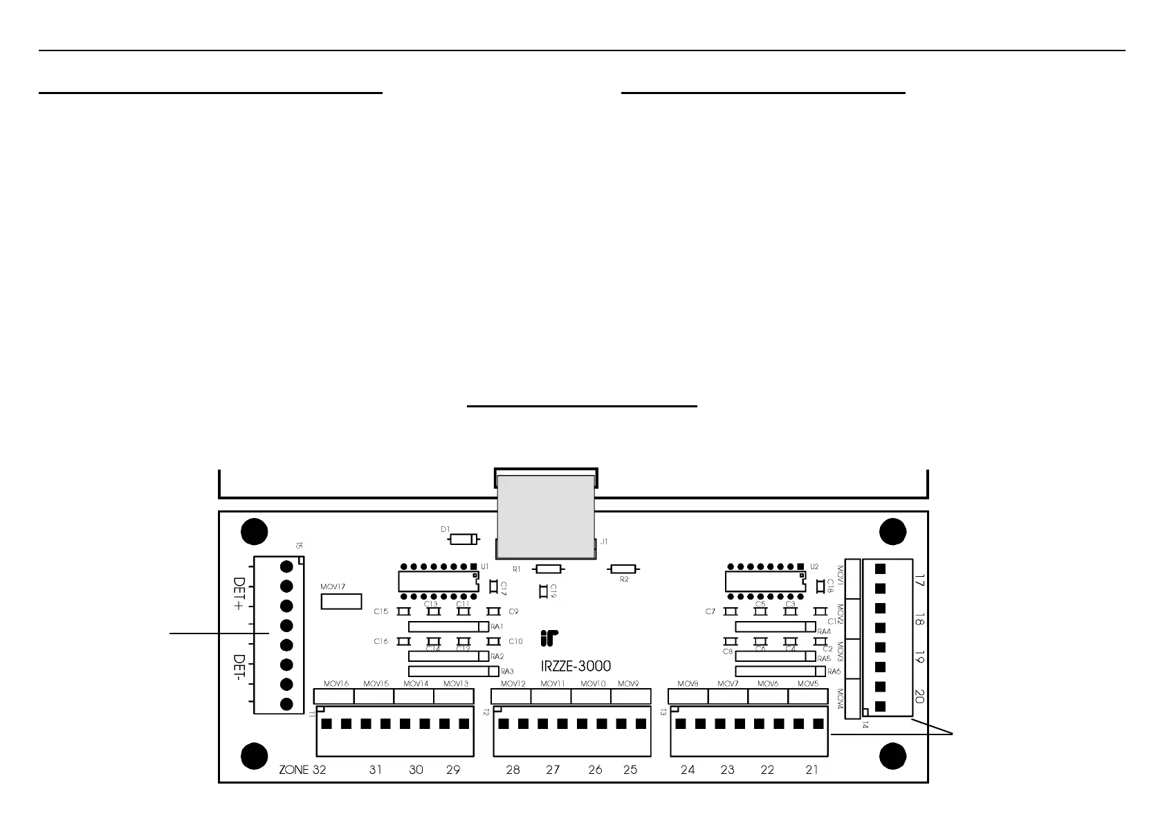
16 Zone Expansion board layout
Connects to Expander Module J1
via cable supplied.
Universal Expander Module PCB
Mounting the 16 Zone Expansion Board
1) Remove the power and disconnect the battery from the Universal Expander Module.
2) Mount the 16 Zone Expansion board in the Universal Expander Module enclosure.
A variety of mounting hardware is provided to enable the board to be mounted in the
space provided on the chassis or above the Universal Expander if necessary using the
35mm metal standoffs. (see Parts List opposite)
The board is secured onto the standoffs using the M3 screws provided.
3) Using one of the ribbon cables supplied, connect J1 on the Zone Expander to the 16
Zone Expansion Board.
Notes:
-Use the short cable whenever possible.
-Do not use an interconnection cable longer than 500mm.
T1 to T4.
Zone Input connections.
Zones 17 to 32.
T5. Detector Power.
Power Supply output for
+12V Detector Power.
Fuse protected via
Expander Module
Detector Fuse.