Revision 2.2 May. 2012. 7
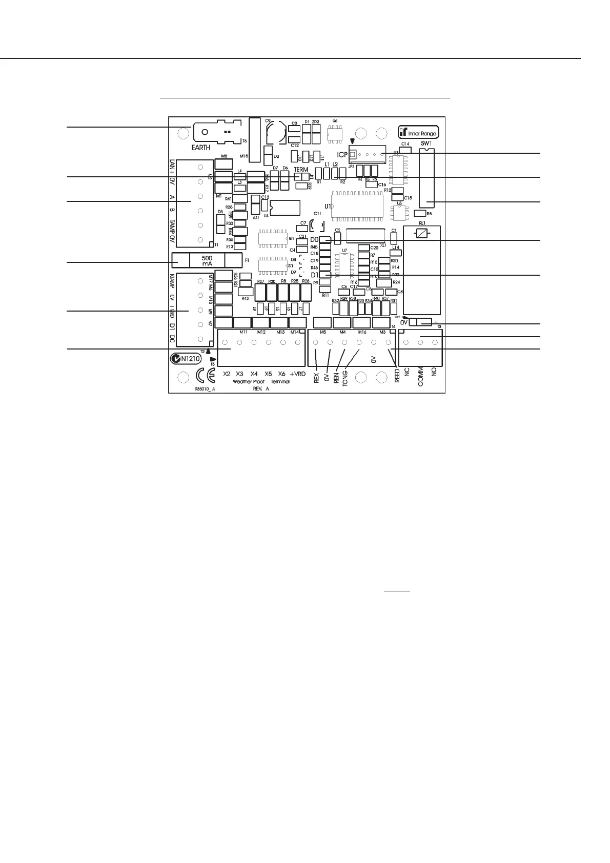
THE WEATHERPROOF TERMINAL MODULE PCB
1
2
3
4
5
6
1. Earth. Connect to building earth or electrical earth.
2. LK1. TERM. Fitted only if this unit is one of the two
furthest modules from the Control Module.
3. T1. LAN, External Power & Tamper Switch Connections.
LAN+ LAN +ve connection.
0V LAN 0V (-VE) connection.
A LAN Data A connection.
B LAN Data B connection.
TAMP Tamper Switch input.
0V Ext. Power Supply -VE input.
& Tamper switch 0V return.
See “LAN & Power Supply Wiring” on page 4.
4. F1. 500mA FUSE M205. Do not substitute higher value.
5. T2. Keypad & Reader connections.
KTAMP Keypad tamper connection.
0V Keypad/Reader 0 Volt (-ve) connection.
+VRD +12V Keypad/Reader power.
D1 Keypad/Reader Data 1’s input.
D0 Keypad/Reader Data 0’s input.
6. T5. Auxiliary Outputs.
X2. Keypad Lamp 1 (CODE) control.
X3 Keypad Lamp 2 (ARMED) control.
X4 Spare. May be used for keypad beeper.
X5 Spare.
X6 DOTL Warning (If enabled. See pages 2-3)
+VRD +12V Auxiliary power. (Not required for
Auxiliaries connected to the keypad)
7. JP3. Factory use only.
8. L1 (RX) LAN Data Transmit & FAULT DIAGNOSIS
L2 (TX) LAN Data Receive & FAULT DIAGNOSIS
9. DIPswitch SW1: (See table on page 6)
Switch 1-6. Module number.
Switch 7. Keypad tamper input polarity.
Switch 8. Lockout attempts.
10. D0 Keypad/Reader Data 0’s indication.
11. D1 Keypad/Reader Data 1’s indication.
12. LK2. Lock relay Common contact voltage selection.
Only use when switching low-current non-inductive loads.
When controlling locks, connect the lock as shown on
page 5 and do not fit this link.
Not fitted. Common contact is voltage-free.
+ Common contact is +12V.
0V Common contact is 0V.
13. T3. Lock Relay Connections. (Rnn:X01)
See “Lock Wiring” on page 5.
14. T4. Input connections.
REX Exit Button Input. *2
0V 0 Volt return for Input connections.
REN Entry Button I/P. *2
TNG 1 Optional Tongue Sense I/P. *1 & 3
OR Zone 6 I/P.
REED Reed Switch Input. *1 (Zone 1 I/P)
*NOTES:
1. End-of-line (EOL) Resistors required.
2. EOL’s NOT required. See Note 4 on page 1.
3. “Tongue Sense” selected in Reader Module options.
7
8
9
10
11
12
13
14
 Loading...