Revision 2.2 May. 2012. 3
Installation
1. Choose suitable mounting locations for the Keypad and PCB assembly.
a) Installation environment requirements are as follows:
Module PCB: 0º to 40º Celsius and 15% to 85% relative humidity (non-condensing).
Keypad: -30º to +60º Celsius and 0 to 95% relative humidity (non-condensing). Moisture & Dust rating = IP65.
b) Ensure that the keypad is at a convenient height for viewing the lamps and ease of use. (e.g. average shoulder height)
c) Ensure that the keypad cable can be terminated into the PCB connectors securely and without strain.
2. Mounting the Keypad. Keypad.dimensions: Height: 120mm Width: 65mm Depth: 27mm
a) Remove the screw from the bottom of the housing and separate the back plate from the keypad.
b) Screw the back plate onto the mounting location. (A self-adhesive drilling template is provided)
The wall plugs and counter-sunk screws provided in the Installation Kit may be used on appropriate surfaces.
Distance between mounting hole centres: 83.5mm (pre-drilled mounting holes)
Mounting hole diameter: 4mm (For 3.5mm, 5/32” or ANSI #6 screw)
c) Refit the keypad to the back plate and secure with the original screw, or the special security screw provided in the Installation
Kit. A right angle (L-shaped) tool is also provided in the kit for the security screw.
3. a) The PCB assembly can be mounted in one of the following enclosures, or another suitable enclosure using the 4 self adhesive
PCB standoffs provided, or other suitable PCB standoffs. PCB dimensions: Length: 96mm Width: 96mm
- Small Low Profile Enclosure. P/N: 995200 or P/N: 995200PE (With Built-in Power Supply)
- Plastic Enclosure. (Off-white) P/N: 990045WH
b) One or two “Normally Closed” Tamper switches may be fitted to the enclosure before it is mounted, and wired in parallel
between the “TAMP” and “0V” terminals on T1. (Switch is Open cct when plunger depressed)
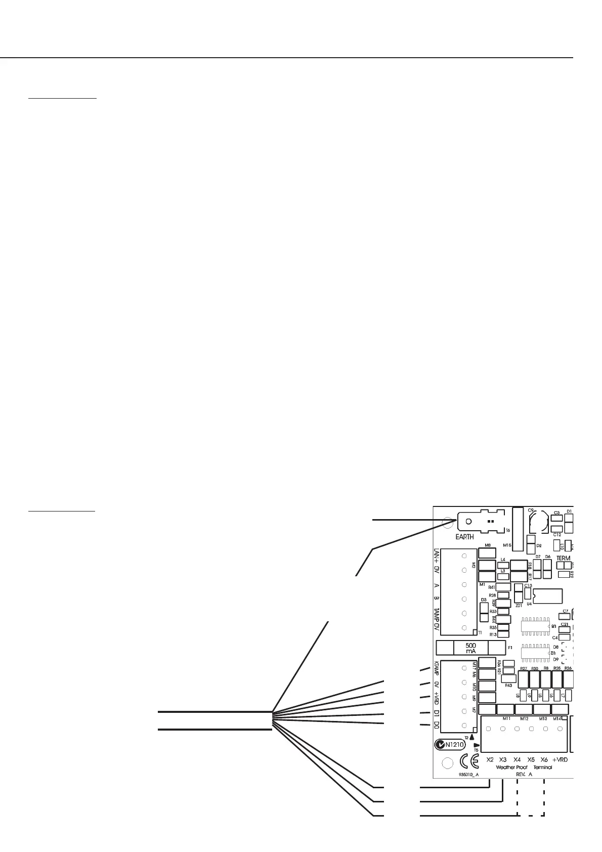
4. Connect the keypad cable to the PCB using the plug-on screw terminal connectors. See diagram below.
The keypad pigtail cable may be extended using shielded, multicore data cable (NOT twisted pair) up to a length of 30 metres
with 7/0.20 cable, or 60 metres with 7/0.30 cable.
The cable may also be trimmed if necessary, but should not be trimmed to less than 500mm. See Important Note 7 on page 1.
5. The Module Number is set to a number between 1 and 64 using DIPswitches 1 to 6 as required. See table on page 6.
Note that the Module must be powered down when making any DIPswitch setting changes.
Purple
Black
Red
White
Green
Brown
Blue
Yellow
Keypad cable
Red +12V power supply
Black 0V power supply
White Data 1’s
Green Data 0’s
Brown LED 1 -Green
Blue LED 2 -Red
Yellow Beeper. See Note below.
Purple Tamper
Shield * Earth (Connected to case only)
Shielded Multicore
cable from keypad
To building earth
Shield. *
DO NOT
connect to 0V
NOTE: Beeper Connection (Yellow Wire).
Connect to:
- X6 for DOTL Warning (If “Warn DOTL” option
enabled in Reader Module programming)
- X4 for other applications.
See
Note
 Loading...