WW
WW
W
eatherproof Teatherproof T
eatherproof Teatherproof T
eatherproof T
erminal Module.erminal Module.
erminal Module.erminal Module.
erminal Module. Installation Manual.
2
Installing the Weatherproof Terminal.
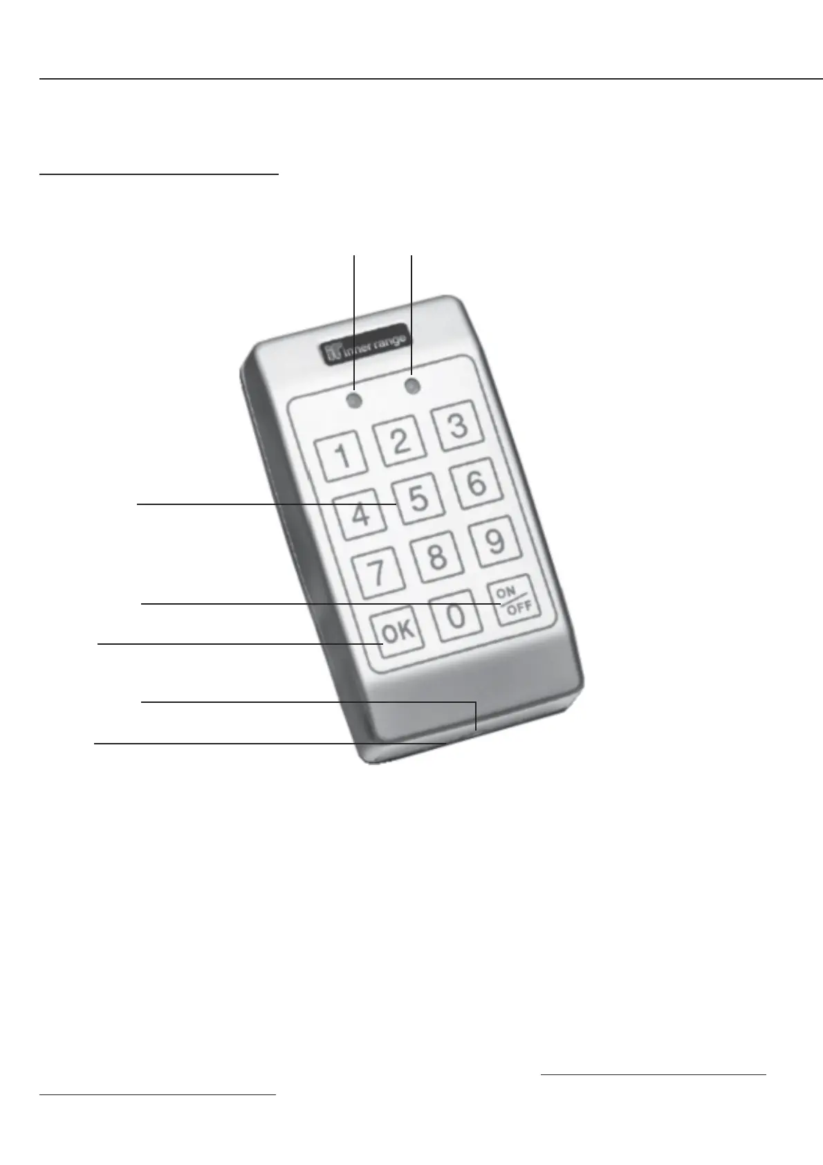
Keypad layout and functions.
Lamp 1 Green CODE (Logged on) On while User is logged on.
Lamp 2 Red ARMED Current Area status. Only displayed while logged on. On = Area On.
Numeric keys PIN code Entry. When logged on, pressing the 0 key will logoff the User.
OK key. Pressed after PIN code to logon.
Door access request while logged on.
ON/OFF key. Toggle Area state while logged on.
Beeper. Beeper control wire (Yellow) may be connected to Auxiliary 6 (X6) to provide a DOTL Warning (If the
“Warn DOTL” option is enabled in Reader Module programming), or to Auxiliary 4 (X4) to provide
other features such as Entry/Exit delay warning, etc. (Rxx:X04 will need to be assigned to the required
Area Auxiliary/s)
Lamp 1. Green Lamp 2. Red
CODE ARMED
Numeric keys
ON / OFF key
OK key
Security screw
Beeper
NOTE:
The keypad is fitted with a 1 metre pigtail cable.
This cable may be extended or trimmed to suit the installation, but note that if trimmed to less than 500mm the
warranty on the keypad will be void and any repair or replacement will incur a charge.