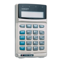
WW
WW
W
eatherproof Teatherproof T
eatherproof Teatherproof T
eatherproof T
erminal Module.erminal Module.
erminal Module.erminal Module.
erminal Module. Installation Manual.
8
Due to on-going product development this manual is subject to change without notice.
© Inner Range Pty Ltd. 2006 - 2012. Part No: 635010
Specifications
Electrical.
Power Supply Input: 11V to 14V DC
Current Consumption. Standby: 40mA.
Logged on: 45 to 55mA.
X01 (Lock relay) active only. 72mA.
All Auxiliaries active: (Lock relay, keypad lamps and beeper all on) 180mA. (Beeper = 90mA)
(These figures do NOT include current drawn by any Reader connected, or by any device connected to the Auxiliary outputs other than
the weatherproof keypad connections)
NOTE: Allow 50 to 120mA for small Prox Reader (~10cm range)
Allow 120 to 180mA for standard Prox Reader (~15cm range)
These values are general approximations.
See information supplied with Reader for actual current consumption.
Lock Relay Contacts:
Voltage: 30V DC maximum.
Current: 750mA maximum.
Fuse Protection: 500mA Reader Power Fuse. Reader current must not exceed 300mA.
ALWAYS REPLACE WITH SAME FUSE TYPE AND VALUE!
Keypad Cable Length: The keypad pigtail cable may be extended using Shielded, multicore data cable (NOT twisted pair)
up to a length of 30 metres with 7/0.20 cable, or 60 metres with 7/0.30 cable.
Physical.
Installation Environment.
Module PCB: 0º to 40º Celsius and 15% to 85% Relative humidity (non-condensing)
Keypad: -30º to +60º Celsius and 0 to 95% relative humidity (non-condensing). Moisture & Dust rating = IP65.
PCB dimensions:
Length: 96mm Width: 96mm
Keypad dimensions:
Height: 120mm Width: 65mm Depth: 27mm
Distance between mounting hole centres: 83.5mm
Mounting hole diameter: 4mm (For 3.5mm, 5/32” or ANSI #6 screw)
Programming Summary
The Module is programmed similar to a Single Door Access Module with the following variations:
- Reader Purpose must be set to “Door Control”
- Reader Format must be a Wiegand format.
- Reader Keys must be set to “IR Weather” which configures correct Auxiliary operation for the CODE and ARMED lamps, and
enables support for special operations such as Card & PIN mode.
- Reader Arm Mode determines the Weatherproof Terminal Area Arm/Disarm Control operations.
-None. No Arming/Disarming.
-Extra Area if PB. User’s Extra Area can be Armed/Disarmed.
-Entry Area if PB. Weatherproof Terminal’s “Associated Area” can be Armed/Disarmed.
- Reader “Associated Area” is an option introduced specifically for the Weatherproof Terminal, that defines the Area to be
controlled by this Weatherproof Terminal if the “Entry Area if PB” option is selected.
- Access Group Entry Mode or Exit Mode can be set to any option in Control Module Firmware V5.7 or later. “Card Only” and
“Card & PIN” are not supported in V5.6 Firmware.
- Backup Cards and a Card Cache are not supported.
Operations Summary
This table shows the operations available with
different Entry/Exit mode and Single/Dual
User options in Access Group programming.
ylnOdraCylnoNIPNIP&draC
resUelgniS seYseYseY
resUlauD seYONseY
.snmuloc"ylnONIP"&"ylnOdraC"otrefeR.draCroNIP:eto
N

 Loading...