Revision 2.2 May. 2012. 1
ConceptConcept
ConceptConcept
Concept
4000/5000 4000/5000
4000/5000 4000/5000
4000/5000
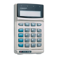
Weatherproof Terminal Module.
P/N: 995010
INSTALLATION MANUAL
Overview
The Weatherproof Terminal Module incorporates an IP65 rated keypad and provides the following operations:
1. Single Door PIN code Access control including the “auto area off” and REX/REN button options.
Note: A Wiegand Reader can also be connected in parallel with the keypad to provide “PIN or Card” operation.
2. Control and status indication of a single “Associated Area” assigned to the Module, or a User’s “Extra Area”.
3. “Card & PIN” and “Card Only” operation. (V5.7 or later) Note that a 12V Wiegand Card Reader must be connected in parallel
with the keypad on the same Weatherproof Terminal Module.
4. Dual User operation supported in “Card Only” and “Card & PIN” modes.
The Weatherproof Terminal supports all Concept 3000/4000/5000 1 to 8 digit PIN codes.
The keypad features a CODE lamp (green), an ARMED lamp (red), numeric keys 0 to 9, OK key and an ON/OFF key.
Beeper feedback is provided for each key press and the beeper can also be controlled by an Auxiliary output.
Three methods of keypad tamper protection are provided:
- A built-in optical device detects removal of the keypad from its mounting surface.
- Presence of the keypad connections is monitored via the data inputs on the PCB.
In addition to this, a Tamper switch input is also provided on the PCB for cabinet tamper monitoring.
- If 3 unsuccessful logon attempts are made in succession, the keypad will be locked out for 60 seconds.
(In Weatherproof Terminal Firmware V1.02 or later, this can be altered to 10 attempts if required by setting DIPswitch 8 to ON.)
IMPORTANT NOTES:
1) Control Module Firmware must be V5.60 or later.
2) The Weatherproof Terminal is enrolled on the LAN and programmed as a Reader Module. (MENU, 7, 2, 4) Programming
options relating to “2nd Door / 2nd Lift”, “2 Door Mode”, “Reader 2...” and “Backup Cards” should not be programmed.
3) Area Arm/Disarm operation is enabled by choosing the appropriate setting in the “Reader Arm Mode” option.
4) Separate Inputs are provided for Exit & Entry buttons. Regardless of whether these inputs are used for Exit or Entry buttons, they
must be programmed for Exit button operation. i.e. Select the “B”utton option in the “Exit Options” of the Access Group
assigned to the Door. Note that Review will therefore always record the direction for the button operation as “Exit”.
5) Zones Rnn:Z02 to Z05, Z07 and Z08 do not exist on the Weatherproof Terminal Module and therefore must not be programmed.
6) Auxiliaries Rnn:X07 and X08 do not physically exist on the Weatherproof Terminal Module and therefore can only be used as
phantom Auxiliaries.
7) The keypad is fitted with a 1 metre pigtail cable. This cable may be extended or trimmed to suit the installation, but note that if
trimmed to less than 500mm the warranty on the keypad will be void and any repair or replacement will incur a charge.
A “Programming summary” and “Operations Summary” is provided on Page 8.
For more details refer to the Programming & Reference Manual V5.6 or later.
Parts List
- Weatherproof Terminal Module PCB assembly.
- PCB Installation Kit in Plastic bag containing:
- 1 x 3 Way Plug on Screw Terminal.
- 3 x 6 Way Plug on Screw Terminals.
- 1 x 5 Way Plug on Screw Terminal.
- 5 x 2k2 End-of-line resistors. (red-red-black-brown-brown)
- 5 x 6k8 End-of-line resistors. (blue-grey-black-brown-brown)
- 1 x 1N4004 protection diode. (For connecting across lock coil)
- 1 x 6.3mm Quick Connect.
- 1 x 500mA Amp Fuse. (Spare)
- 2 x Jumper Link 0.1”.
- Inner Range Weatherproof keypad with 1 metre cable.
- Installation Manual. (This document)
- Keypad Installation Kit consisting of:
- 1 x Self-adhesive drilling template.
Plastic bag containing:
- 2 x Plastic wall plugs
- 2 x Countersunk self tapping screws
- 1 x Countersunk security screw.
- 1 x Right-angle security screw driver.