WW
WW
W
eatherproof Teatherproof T
eatherproof Teatherproof T
eatherproof T
erminal Module.erminal Module.
erminal Module.erminal Module.
erminal Module. Installation Manual.
6
DIPswitch Settings
Note that the Module must be powered down when making any DIPswitch setting changes.
MODULE NUMBERING
The Weatherproof Terminal Module is enrolled on the LAN as a Reader Module (R). The Module number is set to a number between
1 and 64 using DIPswitches 1 to 6. The Module number equals n + 1, where n is the binary number set on DIPswitches 1 to 6.
Module No: DIPswitch: 1 2 3 4 5 6
Binary value: 1 2 4 8 16 32
1 off off off off off off
2 ON off off off off off
3 off ON off off off off
4 ONONoff off off off
5 off off ON off off off
6 ON off ON off off off
7 off ON ON off off off
8 ONONONoff off off
9 off off off ON off off
through to
64 ON ON ON ON ON ON
KEYPAD TAMPER INPUT. POLARITY SETTING (“KTAMP” on connector T2)
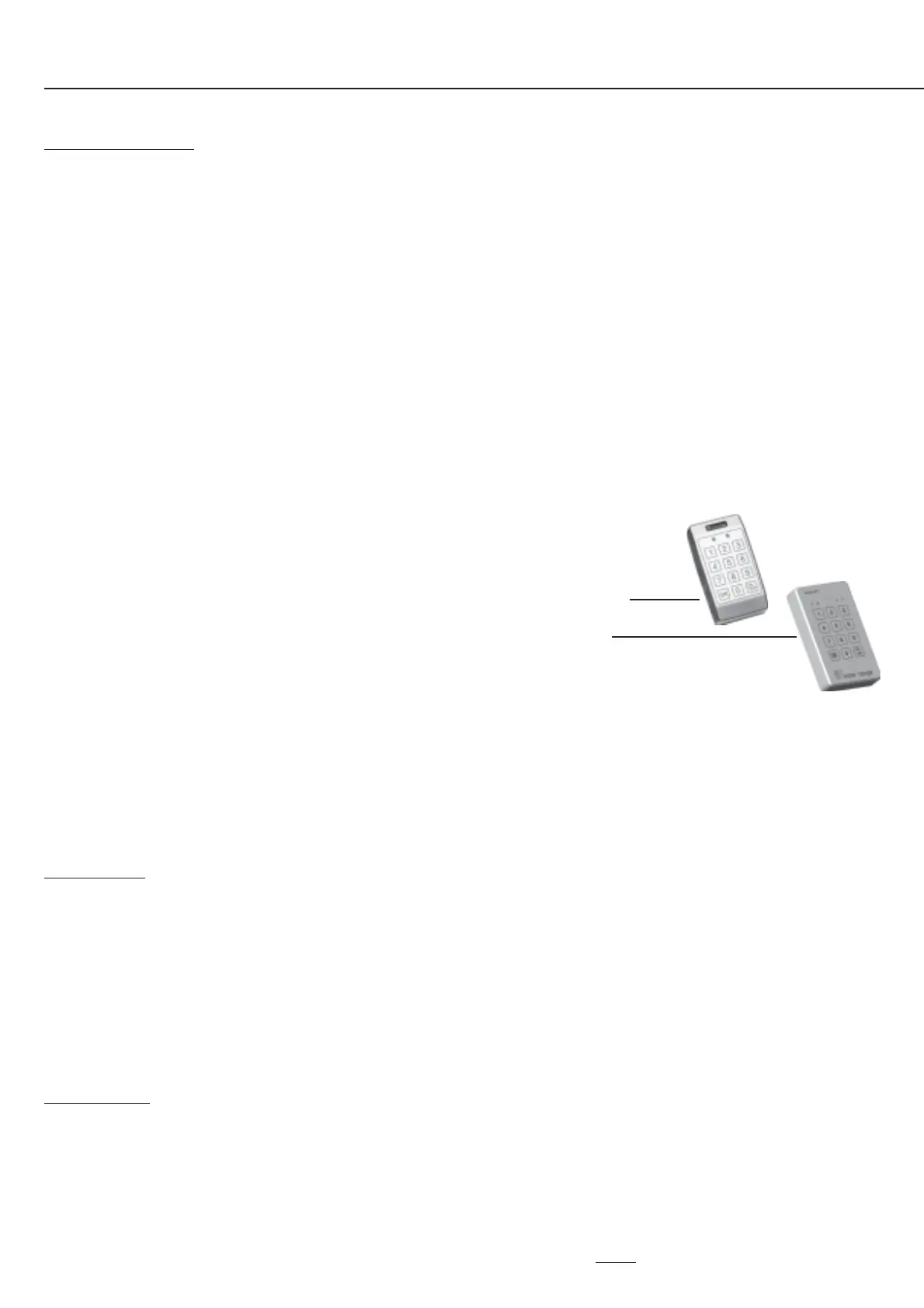
DIPswitch 7. ON (Seal = Low) Setting for current Rosslare Weatherproof keypad.
Weatherproof Terminal Firmware V1.60 or later only.
OFF (Seal = High) Setting for legacy 4-LED Weatherproof keypad.
KEYPAD LOCKOUT
If a number of unsuccessful logon attempts are made in succession, the keypad will be locked out for 60 seconds and the CODE
lamp will flash continuously during the lockout time. DIPswitch 8 determines the number of attempts required for keypad lockout.
DIPswitch 8. OFF 3 attempts.
ON 10 attempts. Weatherproof Terminal Firmware V1.02 or later only.
Note: If an error is made while entering a PIN code, the ON/OFF key can be used to clear the digits entered, so the PIN can be
entered again without registering an unsuccessful attempt.
Fault Lamps
L1 (RX) L2 (TX) EXPLANATION / REMEDY
ON ON Module is un-addressed.
OFF ON Module type unknown. Firmware upgrade required to Control Module.
Flash ON Duplicate Module. This module number is already in use by a module of the same type.
Flash Flash Module number selected is too big for Control Module RAM size. Select a lower Module number.
ON OFF Too many modules on Network for Control Module RAM size.
Alternating Flash EEPROM fault. Return for service.
Link Settings
LK1 TERM Off: Unterminated.
On: Terminated. Only fitted if Modole is one of the two furthest Modules from the Control Module.
LK2 RELAY COMMON CONNECTION Not fitted. Relay common is voltage-free.
+ Relay common is +12V.
0V Relay common is 0V.
CAUTION: Note that this link should only be used when switching low-current non-inductive loads.
When controlling locks, always connect the lock as shown on page 5 and do not fit link LK2.
 Loading...