Revision 2.2 May. 2012. 5
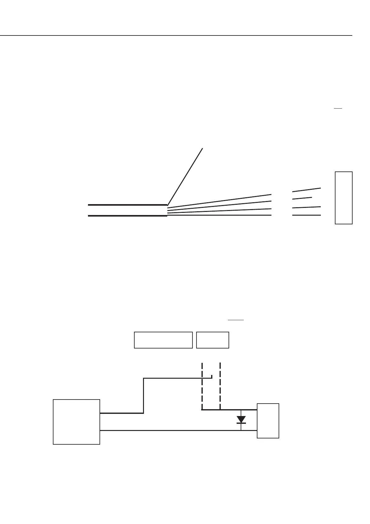
Lock Wiring.
Heavy duty Fig. 8 cable (24/0.20 or 14/0.20) is recommended for all Power & Lock wiring.
CAUTION: A voltage selection link (LK2) for the Lock relay Common contact is provided, and is located next to connector T3.
Note that this link should only be used when switching low-current non-inductive loads.
When controlling locks, always connect the lock as shown below and do not fit link LK2.
REX
0v
REN
TONG
0v
REED
NC
COMM
NO
EXTERNAL
PWR SUPPLY
(BATTERY
BACKED)
-
+
Lock
Strike
1N4004 Protection Diode
(supplied) fitted as close as
possible to the strike.
Cathode (bar) to +VE.
-
+
+VE wired directly to
External Power Supply.
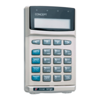
Reader Wiring.
A Wiegand Reader may be wired in parallel with the keypad to provide “Card Only”, “PIN or Card” or “Card & PIN” Door access
operation. See the “Overview” on page 1, and “Programming Summary” and “Operations Summary” on page 8 for more details.
The Reader supply (+VRD) is fixed at 12V.
i.e. A 5V Reader supply is not available and any Wiegand Reader connected must be able to accept a 12V supply.
Readers with Clock and Data output (e.g. Magnetic Swipe Readers), and Readers that will only operate from a 5V supply are not
supported.
LED and/or beeper control wires provided on the Reader can be wired directly to an appropriate Auxiliary output on T5. (Dropping
resistor is not usually required) See information supplied with Reader for LED control details.
RELAY T3
(Rnn:X01)
Power
to Lock
Power
to Un-Lock
or
T4
KTAMP
0V
+VRD
D1
D0
T2
Black
Red
White
Green
Multicore cable from
Wiegand Reader.
NOTE: Use shielded Data cable. Tycab DMC6702,
Garland MC7-6S, etc. DO NOT use twisted pairs!
Shield.
Connect to Earth terminal if earthing is provided.
Connect to 0V if no earthing is provided.
 Loading...