EasyManua.ls Logo

Innotek Auto Backer User Manual

Innotek Auto Backer
5 pages
To Next Page IconTo Next Page
Page #1 background imageLoading...
Page #1 background image
Auto Backer Instructions
1. Unpack Unit
Remove backing dog from box and remove any loose packing material.
2. Power Up/Install Antenna (if applicable)
Transmitter – Insert standard 12v alkaline battery in the transmitter with the positive
(+) side out. Replace metal cap.
Backing dog receiver – Install antenna on the backing dog receiver.
The unit is equipped with a rechargeable battery. The battery can be charged while left
in the unit, or can easily be removed by loosening two screws, allowing you to charge
the battery at a more convenient location. The unit is shipped with the battery
charged. When the battery becomes fully discharged, allow 12-14 hours on the charger
for a complete recharge.
Note – the unit is shipped with the
positive battery lead disconnected. You will
need to remove the tape from the lead
and connect it to the rechargeable battery
before proceeding with charging and operation.
3. Match the Transmitter and Receiver (
With the Transport
Latch disengaged, see Fi
g 3
below)
Step 1 - Pres
s and hold th
e RED button
on the
launcher receiver -- a green LED light will
flash and then go out.
Step 2 - Continue holding the RED button down, and a yellow LED will stay on for
about two seconds. Release the RED button and the LED will start to flash yellow,
indicating the backing dog receiver is in the program mode.
Step 3 - Press and release the handheld transmitter button you want to use to activate
the backing dog. A green LED light will flash on the backing dog receiver indicating the
unit is properly programmed and ready to use.
Step 4 - Repeat the above to program additional backing dogs to the same transmitter, making
sure you choose a different transmitter button for each additional unit, or if
using the "
tw
o-button" transmitter, move the slide switch located on the left side of
the transmitter to the alternate position. You may then program a second backing dog
(or launcher) with the single button.
Question and Answer IconNeed help?

Do you have a question about the Innotek Auto Backer and is the answer not in the manual?

Innotek Auto Backer Specifications

General IconGeneral
BrandInnotek
ModelAuto Backer
CategoryPet Care Product
LanguageEnglish

Summary

Unpack and Prepare Unit

Transmitter Power Up

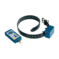
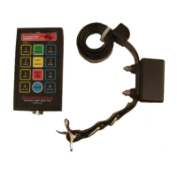
Install a 12V alkaline battery into the transmitter with the positive (+) side out and replace the metal cap.

Receiver Antenna Installation

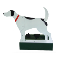
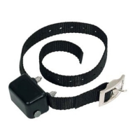
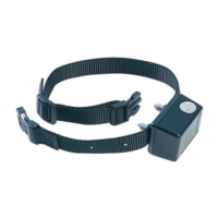
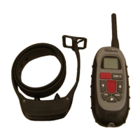
Install the antenna on the backing dog receiver unit.

Rechargeable Battery System

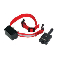
The unit has a rechargeable battery that can be charged in or out of the unit.

Initial Battery Lead Connection

Connect the positive battery lead to the rechargeable battery after removing tape.

Match Transmitter and Receiver

Initiate Pairing Mode

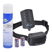
Press and hold the RED button on the launcher receiver until the yellow LED flashes.

Confirm Programming

Press the transmitter button; a green LED on the receiver confirms programming.

Program Additional Dogs

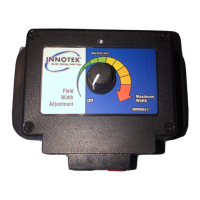
Program more dogs using different transmitter buttons or the slide switch.

Battery Charging and Maintenance

Positive Battery Lead Connection

Ensure the positive lead is connected to the battery terminal.

Charging the Unit

Charge the sealed battery fully before use; charge every 60 days for longevity.

Charger Indicator LED

Some chargers have an indicator LED; use 12-14 hours charge time if none.

Unit Setup and Operation

Transport Latch and Silhouette

Undo the transport latch to raise the silhouette; it must move under its own power.

Link Bar Attachment

Mounting screw (3mm hex driver) secures components. Be careful not to lose washers.

Troubleshooting Unit Operation

9-Volt Battery Replacement

Replace the 9-volt battery in the radio receiver if the unit acts up.

Unit Stops Unexpectedly

Check link bar attachment, 9-volt battery, main battery charge, and connector.

Limit Switch Roller Adjustment

Verify the rotating bar trips the limit switch roller for proper operation.

Limit Switch Setup Details

Limit Switch Body Position

View showing the position of the limit switch body relative to the rotating bar.

Limit Roller Adjustment

Use a 3mm hex driver to adjust the limit roller screw for proper function.

Related product manuals