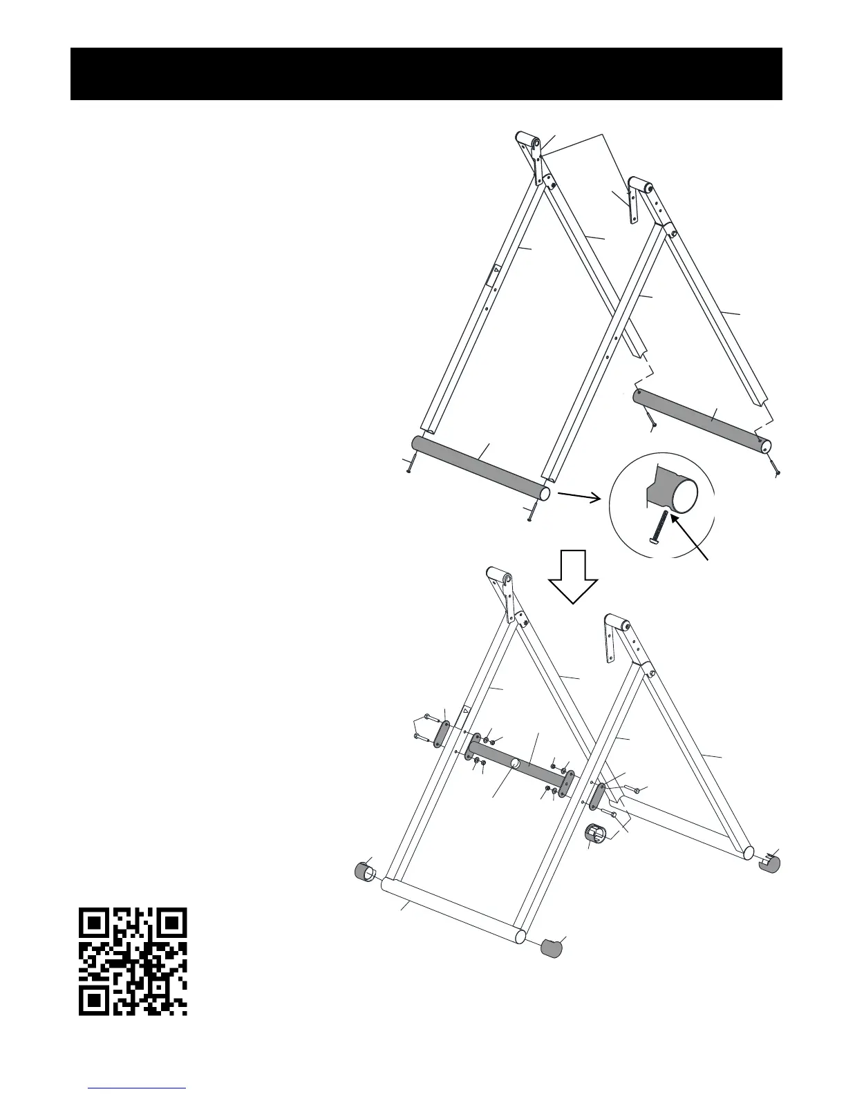
Step 1 – Base Frame Assembly
5
PLEASE NOTE:
RIGHT (R) Indicates right side while using the
inversion table, not facing it.
LEFT (L) Indicates left side while using the
inversion table, not facing it.
NUTS (21) are Nylon Lock Nuts. To tighten,
you need two wrenches.
Lay the Right Base Frame (8R&9R) and
the Left Base Frame (8L&9L) on the floor
with the Connecting Brackets (11R&11L)
facing each other. Make sure the
indented holes on the Bottom Tubes (1)
are facing downward and attach one
Bottom Tube (1) to the Front Base Frame
(9R&9L) using 2 Bolts (32). Attach the
other Bottom Tube (1) to the Rear Base
Frame (8R&8L) using 2 Bolts (32).
DO NOT tighten Bolts (32) until the
Cross Bar (12) is attached.
Make sure the Rubber Stopper (34) on
the Cross Bar (12) is facing out and
attach the Cross Bar (12) to the Front
Base Frame (9R&9L) using 4 Bolts (20)
and 2 Metal Support Plates (54), 4
Washers (19) and 4 Lock Nuts (21).
NOW Tighten all Bolts (32&20).
Insert 4 Base Frame End Caps (31)
into both Bottom Tubes (1).
Unfold the Front Base Frame (9R&9L)
from the Rear Base Frame (8R&8L)
and let it stand on the floor.
Installation Guidance Video DOES NOT replace Owner’s Manual. Please be
sure to read the Owner’s Manual in its entirety.
https://youtu.be/72kV8tdOlC0 or search “Innova ITM4800 Installation Guide” on YouTube.com
Indented
Hole


 To Next Page