1 LC-2
The LC-2 is a controller that controls a wideband O2 lambda sensor to
measure O2 content in exhaust gasses. In this section we will spend a
moment getting familiar with the LC-2 lambda controller.
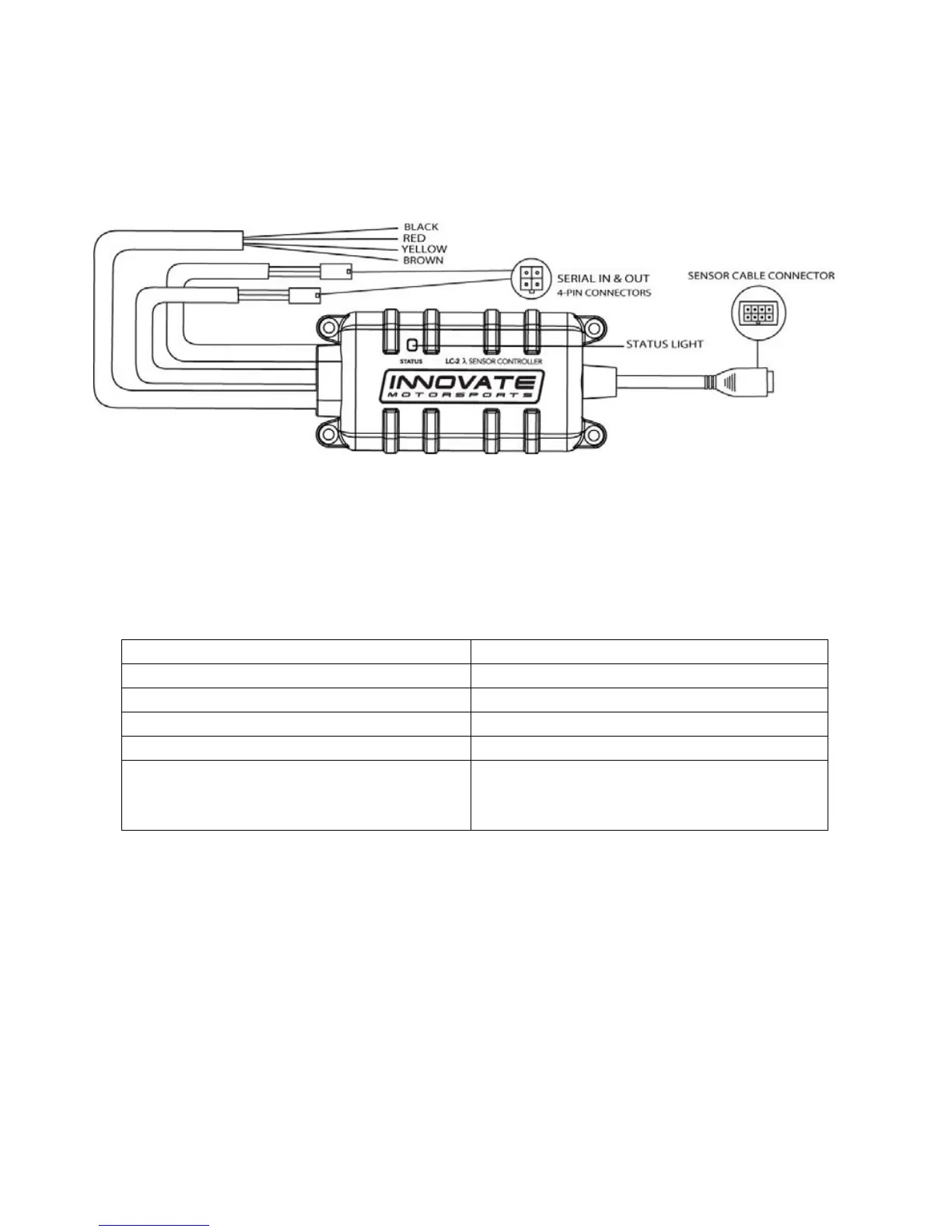
1. Statu
s Light – The LC-2 status light indicates the controller’
s
operational
status. When the controller is powered, the status lig
ht will
light up gre
en for 2 seconds indicating
controller initialization.
After the initialization, the st
atus light will light will blink or light up
constant up to indicate one of the following operational status conditions:
Light Status Definition
No Light No power to the LC-2
GREEN, flashing twice a second Sensor Warm-up
GREEN, series of quick flashes Sensor Calibration
GREEN, solid LC-2 operational, taking readings.
RED, series of flashes followed by a
pause
The number of flashes indicates an
error condition. See Appendix for
error code details.
2. Sensor Cable Connector – Mates the sensor cable to the O2 sensor.
3. Wiring – The
LC-2’s wiring is very straight forward. All that is neede
d
for basi
c installation is power (red) and ground (bla
ck). The two
config
urable analog output wires (one yellow and one brown) ca
n be
use
d to feed external Standalone ECUs, 3
rd
party data loggers, and
AFR display gaug
es.
4.
Serial IN & OUT Connectors – The LC-2’s serial conne
ctors are
utilized
when needed to program analog output settings, data log vi
a
the Log
works software with a Windows PC, or to daisy chain
with other
Innovate Motorspo
rts’ devices
.