Brief Introduction
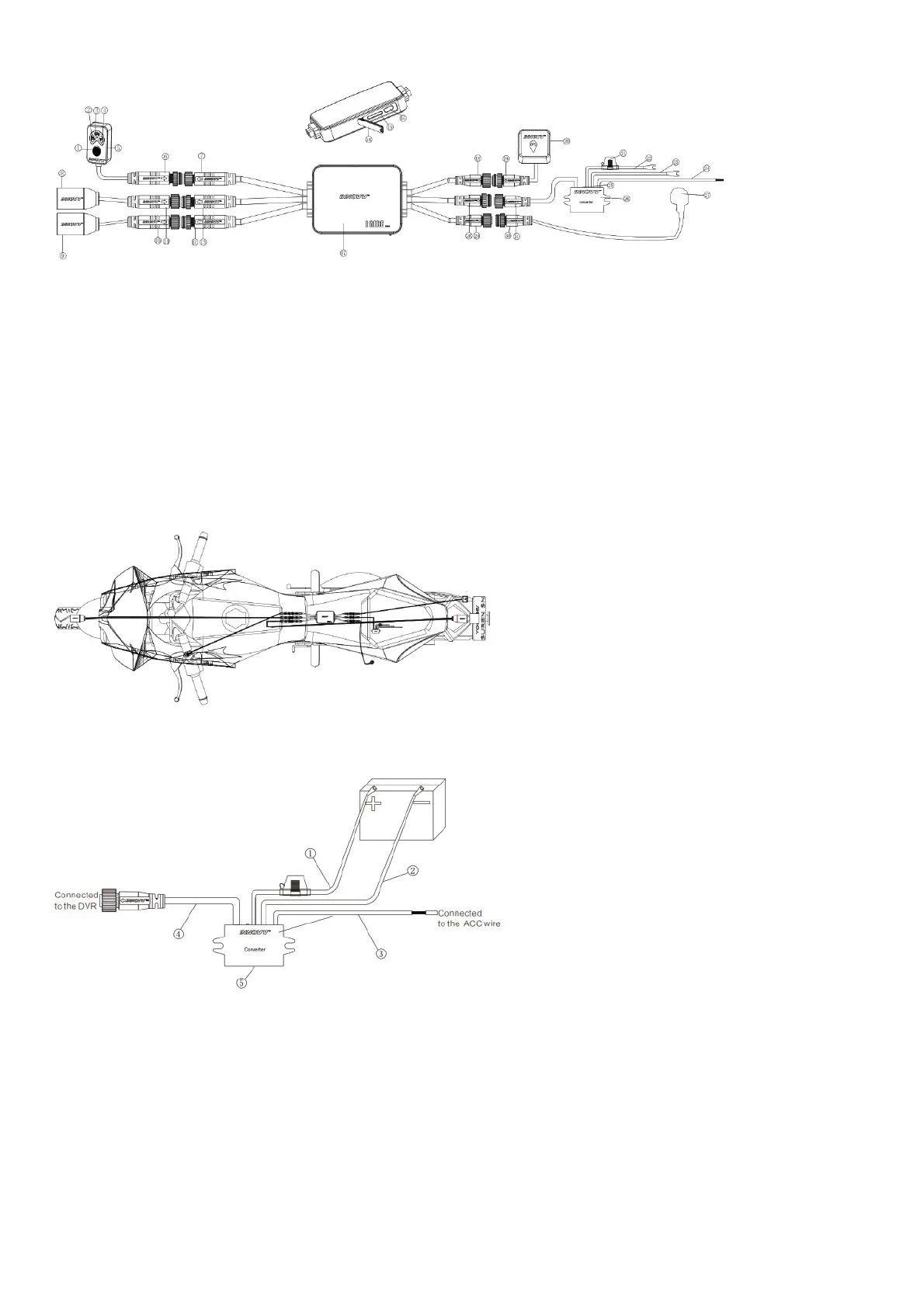
1. Function Button 12. Rear Camera Cable Connected to DVR (6-pin male) 23. Negative Terminal of Power Supply
2. Recording Indicator 13. Front Camera Cable Connected to DVR (6-pin male)
24. ACC Wire (Offers 12V switch power source after
ignition)
3. GPS Indicator 14. Waterproof Silicone Plug
25. Power Indicator (Blue light on means there is 5.3V
voltage)
4. Wi-Fi Indicator 15. TF Card Port 26. DC Converter
5. Remote Control 16. USB Port 27. Microphone
6. Remote Control Cable (6-pin male) 17. DVR 28. Power Input Cable Connected to DVR(3-pin male)
7. Remote Control Cable Connected to DVR(6-pin female) 18. GPS Cable Connected to DVR(3-pin female) 29. Microphone Cable Connected to DVR (2-pin female)
8. Front Camera 19. GPS Cable (3-pin male) 30. Microphone Cable (2-pin male)
9. Rear Camera 20. GPS Module 31. Power Output Cable (3-pin female)
10. Rear Camera Cable (6-pin female) 21. Fuse Holder
11. Front Camera Cable (6-pin female) 22. Positive Terminal of Power Supply
Motorcycle installation Demo
The Installation Guide
Converter Installation
1. Red wire (connected to the positive of battery) 4. Power output cable (connected tothe DVR)
2. Black wire (connected to the negative of battery) 5. Converter
3. Yellow wire (connected to the 12V switched power source, like headlight, tail light, horn
and others which are associated tothe ignition)
Camera Installation
Installation Method-1 (With L Bracket)